Pump engineering
Closed-loop circulator selection: how to determine flow and loss
Building height is not pump head in a filled closed loop. Calculate flow from thermal load and head from the critical circuit in a worked example.
Illustrative engineering scenario · Assumptions are stated in the text.
AT A GLANCE
- In a filled closed loop, static elevation balances; calculate critical-path loss.
- Thermal load and design temperature difference set flow, adjusted for liquid properties.
- Test control sensor, valve authority and minimum flow in the same scenario.
Separate closed circulation from open transfer
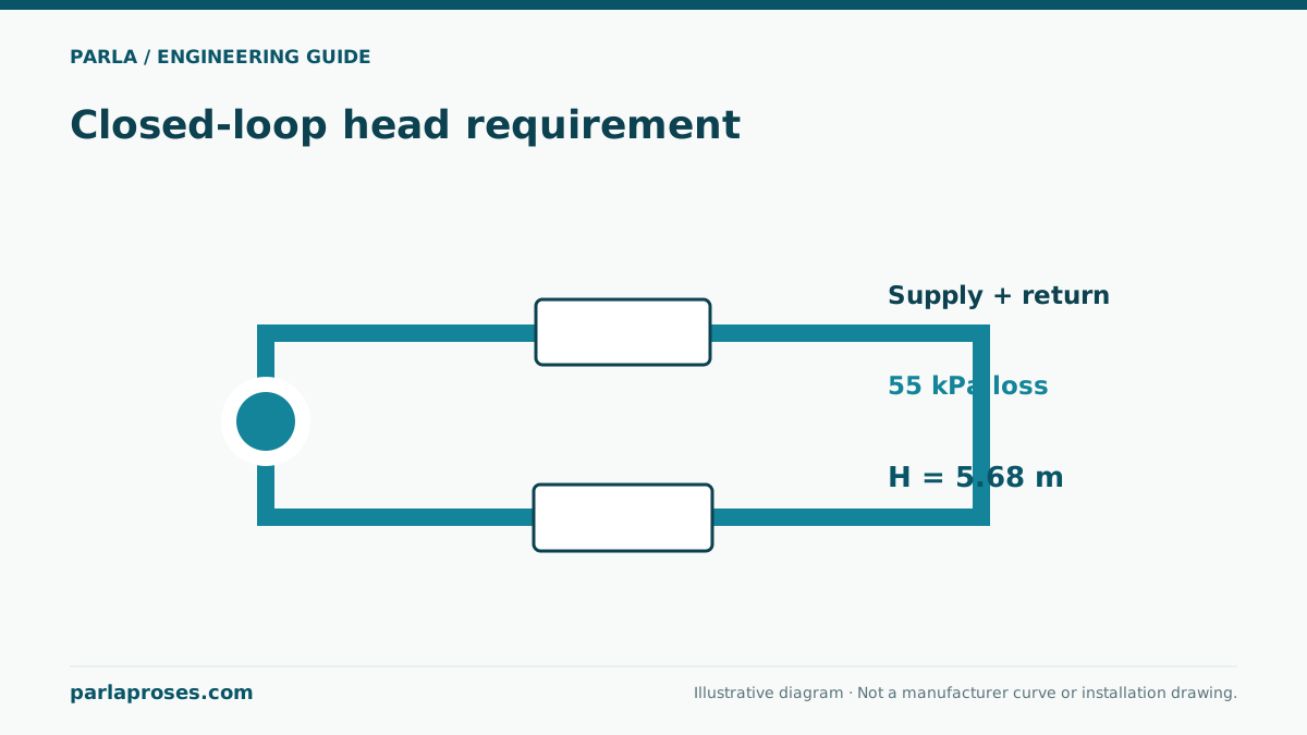
In a filled, hydraulically closed heating or cooling circuit, elevation gained on the supply side is balanced by the descending return water column. The pump does not continually lift the building height; it overcomes losses in the critical supply-and-return path, including pipe, fittings, heat exchanger and control valve. Do not apply this statement to discharge into an open tank, an air break, a free jet or transfer between vessels at different pressures. Such systems can have static or boundary-pressure requirements.
Building height still matters for expansion and fill pressure: maintain suitable positive pressure at the highest point and stay below the permitted maximum at the lowest. Low absolute suction pressure combined with high temperature, air removal and make-up water also need design. Excluding static lift from closed-loop pump head does not make system pressure irrelevant.
Find flow from a 140 kW thermal load
For an illustrative water circuit, take design thermal load 140 kW and supply-to-return temperature difference 10 K. With approximate water specific heat cₚ = 4.18 kJ/(kg·K) and density 1000 kg/m³, mass flow ṁ = 140/(4.18 × 10) ≈ 3.35 kg/s. Volume flow is about 0.00335 m³/s, or 12.06 m³/h. A preliminary selection may use 12 m³/h. This relies on maintaining the design temperature difference at full load.
Adding glycol changes heat capacity, density and viscosity. Recalculate flow for the same thermal load and temperature difference; higher viscosity can also change pipe and exchanger loss. Two-way valves reduce flow at part load, whereas a three-way bypass behaves differently. Examine minimum sustainable flow and control transitions as well as the design point.
Sum pressure loss along the critical circuit
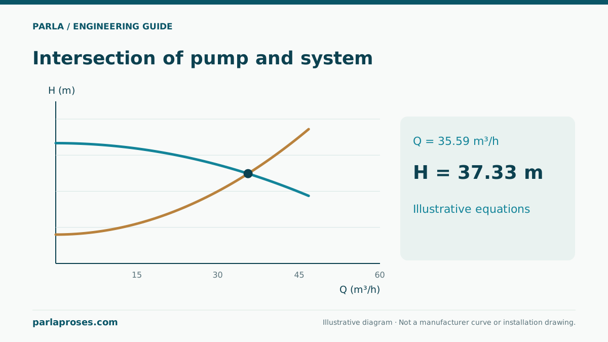
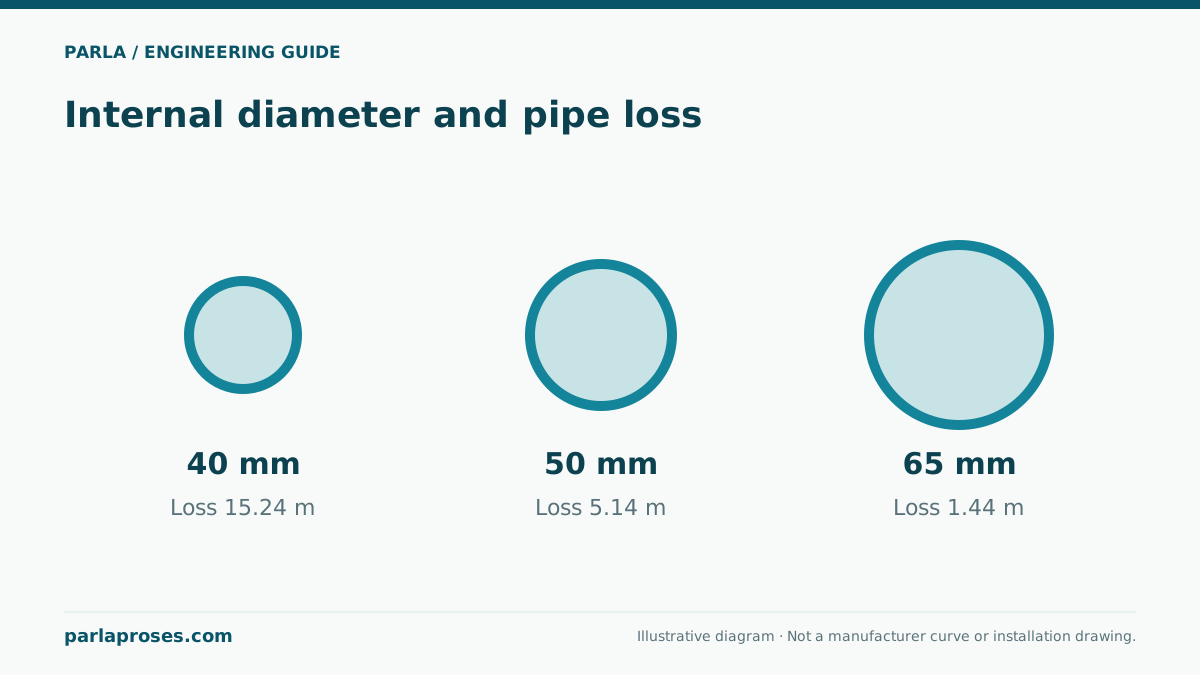
For an illustrative calculation at 12 m³/h, assume 80 m total straight pipe on the critical supply and return, actual bore 50 mm, Darcy factor 0.025 and fitting coefficient sum ΣK = 8. Velocity v = 4 × (12/3600)/(π × 0.05²) ≈ 1.70 m/s, with velocity head v²/(2g) ≈ 0.147 m. The combined pipe and fitting multiplier is 0.025 × 80/0.05 + 8 = 48, giving about 7.05 m. Add critical heat-exchanger loss of 18 kPa ≈ 1.84 m and design control-valve loss of 12 kPa ≈ 1.22 m to reach approximately 10.11 m. Preliminary duty is around 12 m³/h at 10.1 m.
These values do not approve a manufacturer model. Re-evaluate losses using actual bore, viscosity at temperature, fouled-filter condition, heat-exchanger data and valve authority. Sum series elements along one simultaneous critical path; do not add losses of all parallel branches to one another. Design flow allocation and balancing valves determine the most demanding hydraulic path.
| Critical-path component | Loss | Selection use |
|---|---|---|
| Supply+return pipe and fittings | 7.05 m | 80 m, 50 mm bore, assumed coefficients |
| Heat exchanger | 18 kPa ≈ 1.84 m | Update from product data and liquid |
| Control valve | 12 kPa ≈ 1.22 m | Specify together with valve authority |
| Total critical path | ≈ 10.11 m | Compare with curve at 12 m³/h |
Select variable flow and sensor location together
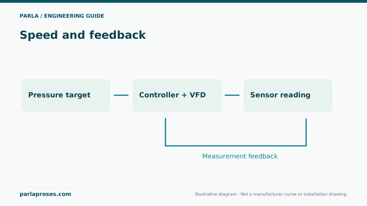
A differential-pressure sensor near the pump does not directly see changing loss in a distant critical branch. Design its position alongside minimum authority at remote valves and the control range. Excessively high differential-pressure setpoints can waste energy and create valve noise, while very low settings may starve the farthest load. Speed reduction may be limited by pump minimum flow, heat source or exchanger minimum flow, and frost protection.
Illustrative application story: an upper-floor coil is under-supplied as all valves open in the morning. Rather than adding building height directly to pump head, measure whether the wrong critical path was chosen, strainer differential pressure, balancing settings and sensor location. The pump alone may not be the cause. This scenario is not a real Parla customer project or proof of performance.
Validate final selection against installation and operation
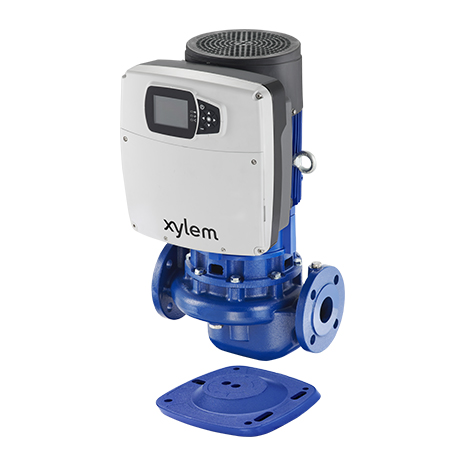
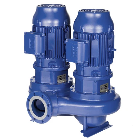
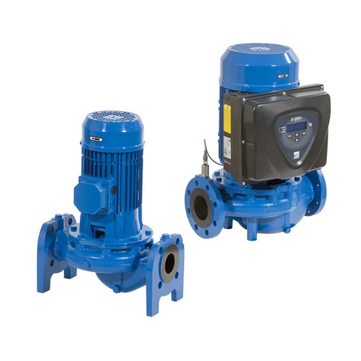
Evaluate inline candidates such as e-LNE or Ebara 3E on exact model curves near 12 m³/h and 10.1 m. Compare speed, efficiency, motor power, liquid temperature, seal and pressure rating. Pipe weight should not be transferred to the casing; specify isolation and check valves for service and reverse-flow cases. Expansion-vessel connection, pump position and resulting pressure distribution affect air separation and cavitation assessment.
During commissioning, record design flow, supply and return temperatures, pump suction and delivery pressures, filter difference and control-sensor reading simultaneously. Failure to achieve target temperature difference is not necessarily a pump fault: check thermal load, coil fouling, valve direction and automation sequence too. Confirm that the calculated critical path matches the actual installed route.
Frequently asked questions
Is building height added to pump head in a closed loop?+
In a filled closed loop, supply and return static elevations balance. The pump covers critical-path losses; building height still matters for fill/expansion pressure and component ratings.
Is flow for 140 kW always 12 m³/h?+
No. It depends on a 10 K temperature difference and assumed water properties. Recalculate with density and specific heat for another temperature or glycol mixture.
Should losses from three parallel branches be summed?+
No. Balance flow in each branch and sum series losses along the critical supply-and-return path. Calculate common headers at simultaneous combined flow.
Does a sensor near the pump ensure pressure at a distant valve?+
Not necessarily. Flow-dependent pipe losses lie in between. Verify sensor location and setpoint against actual differential requirement at the remote critical point.
Apply this assessment to your project.
Share your operating conditions, existing equipment and objective. Let’s assess product selection together with the technical documents.