Pump engineering
Pipe diameter, velocity and pressure loss: a worked selection guide
Compare three actual internal diameters at the same flow, separating pipe and local losses to assess pump head, suction conditions and operating cost.
Illustrative engineering scenario · Assumptions are stated in the text.
AT A GLANCE
- Use actual internal diameter and consistent flow units in velocity and friction calculations.
- Calculate straight-pipe and local losses separately, then add static and process requirements to total head.
- Evaluate a diameter change alongside pump duty point, controls and operating cost.
Start with actual internal diameter, not nominal size
Selecting a pipe diameter is more than matching the pump connection. At the same flow, a smaller cross-section increases velocity and changes both friction and fitting losses. These losses add to the head the pump must provide. A modest diameter difference can affect operating energy over long running periods, while purchase, installation, support and space requirements also enter the decision.
The diameter D used in the calculation is the actual bore for the selected material and wall thickness. A DN designation alone does not provide that value. Different pressure classes of the same nominal size can have different internal diameters. Confirm the preliminary calculation against the technical data for the pipe being ordered. The pump connection size does not require the entire line to use the same diameter.
Use consistent units for velocity and loss calculations
For a circular pipe, mean velocity is v = 4Q/(πD²). Using Q in m³/s and D in metres gives v in m/s. Divide a flow of 12 m³/h by 3600 before inserting it into this formula. Total head loss can be calculated as h = [fL/D + ΣK] × v²/(2g). Here f is the Darcy friction factor, L is straight-pipe length, ΣK is the sum of local loss coefficients and g = 9.81 m/s².
Darcy and Fanning factors are not interchangeable: the Darcy factor is four times the Fanning value. Use either the K method or an appropriate equivalent-length method for elbows and valves, without counting the same component twice. Convert to pressure loss using Δp = ρgh; conversion from metres of liquid to bar depends on liquid density.
Example: three internal diameters over a 60 m line
This illustrative comparison assumes clean-water flow of 12 m³/h, 60 m of straight pipe, a Darcy factor of 0.025 and a total local coefficient of 5. The same internal diameter and flow apply along the entire section. Both f and ΣK are held constant to make the comparison clear; in a real project, determine them again from material, roughness, temperature, Reynolds number and the selected fittings.
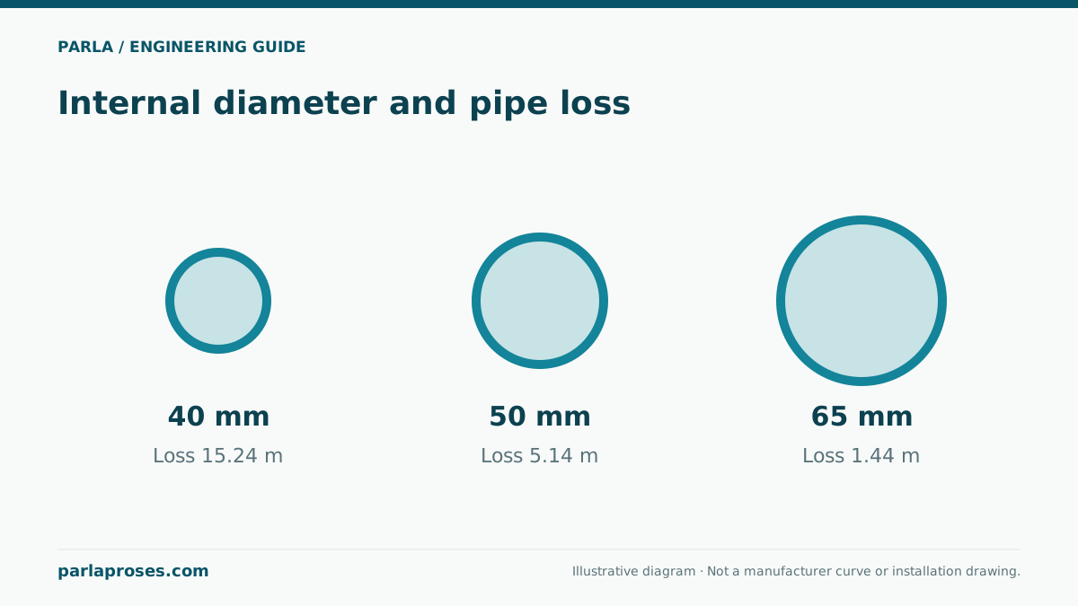
For example, a 50 mm bore gives Q = 0.003333 m³/s and v = 1.698 m/s. The straight-pipe multiplier fL/D is 30, becoming 35 after adding local coefficients. Therefore h = 35 × 1.698²/(2 × 9.81) ≈ 5.14 m. Table values are rounded and are not approved design data for a particular pipe product.
| Actual bore | Mean velocity | Straight-pipe loss | Local loss | Total loss |
|---|---|---|---|---|
| 40 mm | 2.65 m/s | 13.45 m | 1.79 m | 15.24 m; highest resistance |
| 50 mm | 1.70 m/s | 4.41 m | 0.73 m | 5.14 m; intermediate option |
| 65 mm | 1.00 m/s | 1.19 m | 0.26 m | 1.44 m; from unrounded components |
Add pipe loss to the total required pump head
Assume the line operates between two large open tanks with a static elevation difference of 12 m and no other losses. At the target flow of 12 m³/h, required pump head is 27.24 m for the 40 mm bore, 17.14 m for 50 mm and 13.44 m for 65 mm. Add process equipment, filters or required outlet pressure separately where applicable. Pipe loss alone is not the total required head.
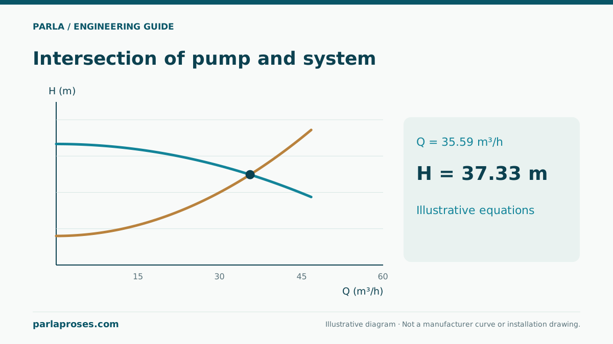
Enlarging the pipe while leaving the existing pump at the same speed generally shifts the duty point toward a higher flow. In that case, the fixed-flow losses in the table do not directly describe the new operation. Recheck the intersection with the new system curve, motor loading and NPSH. In a common header and branched network, use the simultaneous flow through each individual section rather than arbitrarily adding the losses of all branches.
Evaluate energy together with the control method
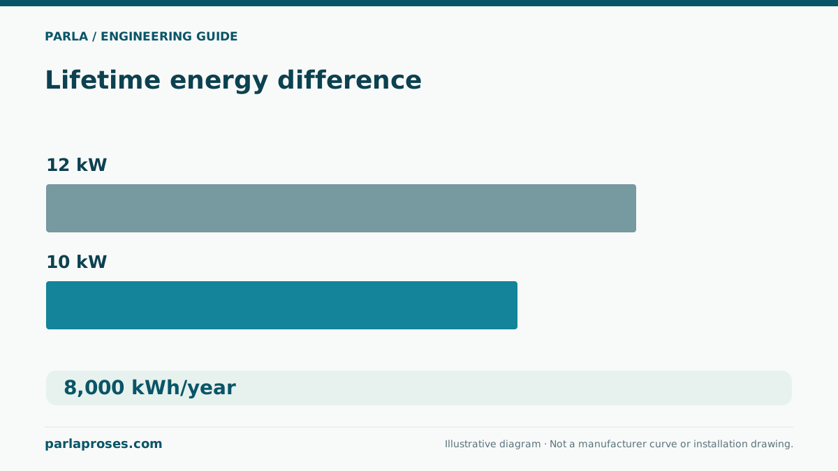
Replacing the 40 mm bore with 50 mm reduces fixed-flow head loss in this example by approximately 10.10 m. With water density of 1000 kg/m³, the hydraulic power difference is ρgQΔh ≈ 0.33 kW. If control maintains 12 m³/h and total efficiency is assumed to be 60 percent in both cases solely for comparison, the electrical power difference is approximately 0.55 kW, or around 2200 kWh over 4000 operating hours annually.
This is not a savings guarantee. Pump efficiency, new speed, operating hours and actual control behaviour change the result. If the avoided pipe loss is simply dissipated in a valve, the expected energy benefit may not materialise. Compare the additional pipe investment using project quotations and the user’s energy tariff; choosing the lowest loss alone does not establish the economic optimum.
Complete the diameter decision with operating conditions
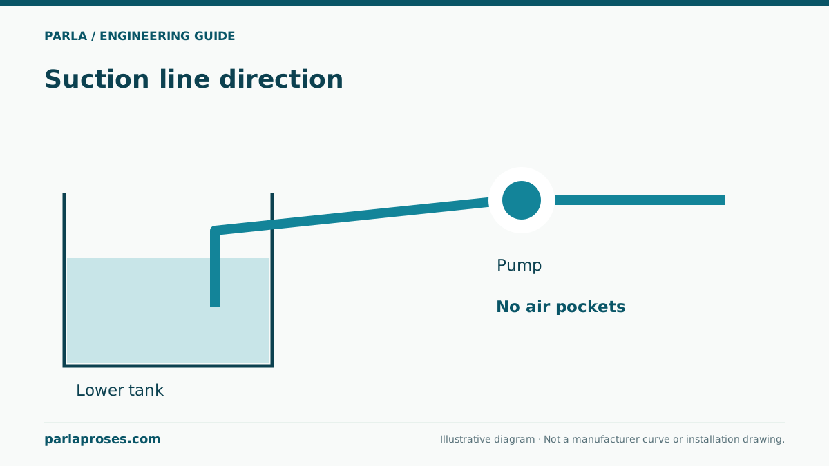
A single velocity limit cannot cover every clean-water installation. Consider noise, line length, operating duration, valve closure, acceptable pressure loss and project requirements together. Pressure-class selection cannot rely on normal friction loss alone: assess static pressure, pump shutoff conditions and transient pressures too. Reduced suction-line loss can improve available NPSH, but air pockets and joint tightness are separate issues. Record the internal diameter, material, length, component list and calculated flow range clearly in the final design file.
Frequently asked questions
Can I treat DN50 directly as a 50 mm internal diameter?+
Not unless the product data confirms it. Interpret nominal size alongside the material standard and wall thickness. Particularly with thick-walled pipes, a small bore difference can materially change velocity and loss calculations.
Why is the total for the 65 mm pipe 1.44 rather than 1.45 m?+
The total is calculated from unrounded straight-pipe loss of 1.1869 m and local loss of 0.2572 m. Adding cells rounded individually to two decimals creates a 0.01 m difference; retain intermediate precision in the design calculation.
Does doubling the flow make the loss exactly four times larger?+
Yes under the assumptions of constant diameter, f and K. In practice, friction factor can change with Reynolds number, and valves or equipment can behave differently. Recheck coefficients and all equipment pressure drops at the new flow.
Does a larger pipe always consume less electricity?+
It reduces loss at the same flow, but electricity consumption depends on the pump’s new duty point and controls. If flow rises freely or surplus head is dissipated in a valve, the calculated fixed-flow benefit does not directly become an energy saving.
Apply this assessment to your project.
Share your operating conditions, existing equipment and objective. Let’s assess product selection together with the technical documents.