Installation and commissioning
Pump suction piping: air pockets, loss and tightness
Assess suction-pipe rise, connections and total loss at the lowest tank level, then correct an illustrative installation fault.
Illustrative engineering scenario · Assumptions are stated in the text.
AT A GLANCE
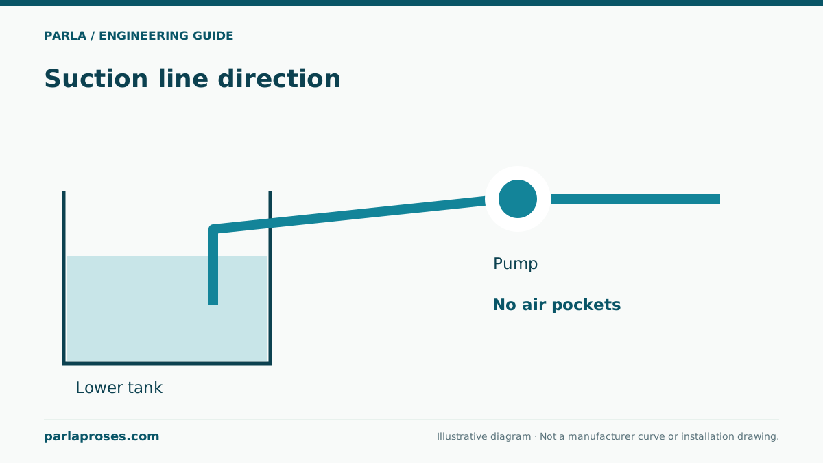
- Route suction lift continuously upward toward the pump without trapping air.
- Calculate loss with actual bore and a fouled-component case.
- Compare NPSHa to manufacturer NPSHr at the same flow and with an appropriate margin.
Suction piping must do more than convey water
Low inlet pressure near vapour pressure can cause cavitation risk, while air drawn through joints can cause loss of prime and unstable flow. They may sound similar, so noise alone cannot diagnose cavitation. The suction route determines actual static elevation, pipe friction and local losses from an open tank to the pump inlet. High points can trap air; one air pocket may matter more than several extra metres of pipe.
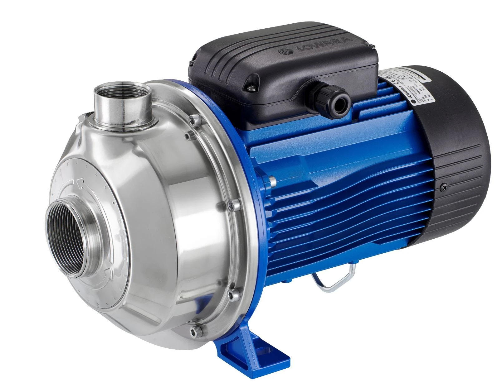
Lowara LS installation instructions emphasise a continuously rising suction pipe toward the pump for suction lift, tight joints, independently supported piping and an NPSH check. This principle does not replace the exact selected pump’s manual. Do not force the pump nozzle to align piping; verify permissible nozzle loads from manufacturer data.
Calculate an 18 m³/h suction line
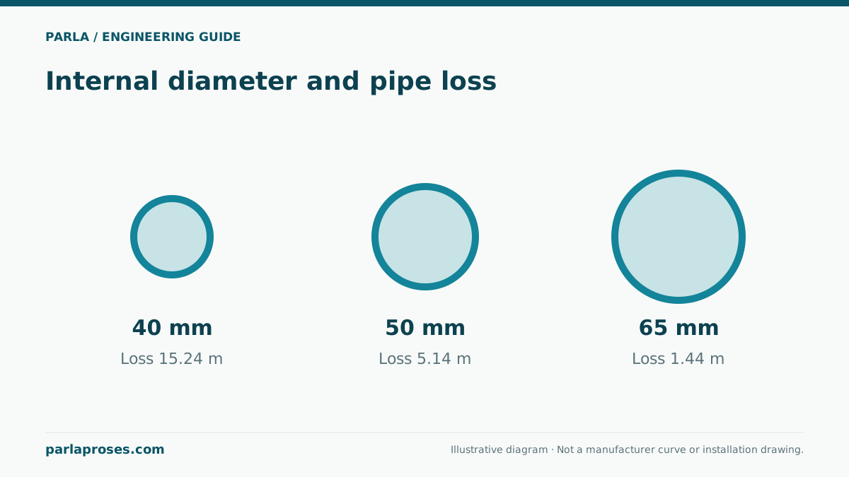
For an illustrative open-tank suction case, assume clean water at 20 °C, target flow 18 m³/h = 0.005 m³/s, actual pipe bore 65 mm and length 8 m. Mean velocity v = 4Q/(πD²) ≈ 1.51 m/s. With assumed Darcy factor 0.025 and combined entry/elbow/valve coefficient ΣK = 3, fL/D ≈ 3.08 and v²/(2g) ≈ 0.116 m. Total suction loss is h ≈ (3.08 + 3) × 0.116 ≈ 0.71 m. Coefficients are teaching assumptions and must be replaced with real pipe and component data.
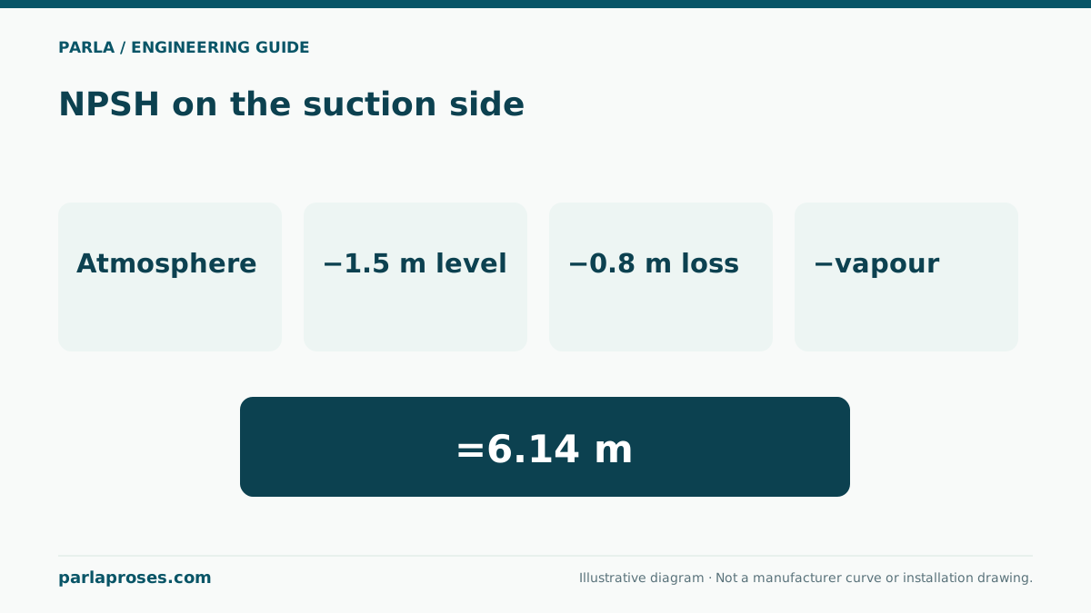
If the lowest free surface lies 2.0 m below the pump reference and the atmospheric-to-vapour pressure head difference at 20 °C is approximately 10.1 m, NPSHa ≈ 10.1 − 2.0 − 0.71 = 7.39 m. Even if a candidate NPSHr curve hypothetically shows 4.0 m at the same flow, the arithmetic difference of 3.39 m is not selection approval. Check manufacturer margin, higher temperature, fouled strainer, altitude and actual lowest level. The NPSHr here is hypothetical.
| Component | Value | Application note |
|---|---|---|
| Flow/bore | 18 m³/h / 65 mm | Use actual bore from pipe data |
| Suction velocity | 1.51 m/s | 4Q/(πD²) |
| Line loss | −0.71 m | Assumed Darcy factor and ΣK |
| Lowest elevation | −2.00 m | Relative to pump datum |
| NPSHa | 7.39 m | Compare with NPSHr at same flow |
Resolve air pockets and reducers on the drawing
For suction lift, the route should rise continuously toward the pump; an up-and-down section invites trapped air. Orient reducers to avoid an air-collecting pocket. A flat-on-top eccentric reducer is a common horizontal-piping solution, but follow the particular pump’s inlet conditions and flow direction. An elbow directly on the nozzle can distort inlet flow; provide the straight approach specified by the manufacturer where required. One universal “5D” rule does not cover all pumps.
If a suction strainer is used, do not calculate only its clean pressure drop; include the loss of a fouled element at the maintenance limit in NPSHa. Keep the isolation valve fully open in normal operation; throttling suction to control flow increases loss. Flooded suction changes the lift geometry, but venting and pressure limits still need confirmation.
Separate two likely causes during commissioning
In a hypothetical application, the pump develops pressure on starting but flow begins to oscillate after a few minutes. First observe tank level and vortex/air entrainment, then check suction joints for tightness. Record suction pressure at the same flow and temperature and compare calculated NPSHa. Rather than adding an arbitrary vent at a high point, plan safe filling and venting allowed by the manual.
Record pipe weight, vibration at the inlet, reducer, valve and strainer access on the site survey. After assembly, document flange alignment, filling, rotation direction and leakage test. This teaching fault story does not claim an actual customer success or completed installation; it demonstrates a measurement-led diagnostic path.
Frequently asked questions
Is an eccentric reducer always mandatory on horizontal suction?+
A geometry that avoids trapped air is needed. Determine reducer type, orientation and inlet distance from the chosen pump manual and layout.
Can I throttle flow with the suction valve?+
It is not recommended for normal operation: it raises loss and lowers available NPSH. Design suitable discharge-side or speed control instead.
Does an NPSHa of 7.39 m approve the pump?+
No. It is an installation value based on illustrative assumptions. You need the candidate’s real NPSHr curve, operating flow, manufacturer margin and limiting conditions.
How can air ingress be distinguished from cavitation?+
Inspect tank vortices, priming and joint tightness; test the NPSH calculation with simultaneous flow, suction-pressure and temperature data. Sound alone is insufficient.
Apply this assessment to your project.
Share your operating conditions, existing equipment and objective. Let’s assess product selection together with the technical documents.