Pump engineering
Pump NPSH and cavitation: calculating suction conditions
Combine temperature, atmospheric pressure and suction losses in one calculation, then compare available NPSH with the pump requirement.
Illustrative engineering scenario · Assumptions are stated in the text.
AT A GLANCE
- Calculate NPSHa from the installation and read NPSHr from the manufacturer curve at the same flow and speed.
- Assess temperature, minimum level and fouled suction components together in credible operating scenarios.
- A positive difference is insufficient on its own; explicitly define the required operating margin in the selection file.
What question does NPSH answer?
Meeting the required flow and head does not prove that a pump has adequate suction conditions. NPSH expresses how far the liquid at the pump inlet is above its vaporisation threshold, in metres of the pumped liquid. Available NPSH, or NPSHa, belongs to the installation; required NPSH, or NPSHr, comes from the selected pump curve at the relevant flow and speed. The same pump can behave differently when tank level or temperature changes.
Vapour bubbles can form when local pressure approaches the liquid vapour pressure. Their collapse in a higher-pressure region can be accompanied by noise, vibration and surface damage. Noise alone does not establish cavitation: air ingress, bearing faults and other hydraulic disturbances require separate assessment.
Define the calculation boundary and signs
For suction from a large tank open to atmosphere, neglecting free-surface velocity, NPSHa = (p_atm − p_vapour)/(ρg) + z − h_suction. Pressures are absolute and expressed in pascals, density is in kg/m³, and g is 9.81 m/s². The elevation z is the free surface relative to the pump reference plane: it is negative when the surface is below that plane. Suction loss includes entry, pipe, elbows, valves and any clean or dirty strainer between the tank and that reference.
For a closed tank, replace atmospheric pressure with the absolute gas pressure above the liquid. Substituting gauge pressure directly for absolute pressure creates a substantial error. Keep the reference plane and treatment of velocity terms consistent with the manufacturer’s data definition.
Annotated example for water at 60 °C
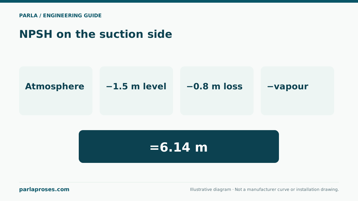
This illustrative example assumes sea-level atmospheric pressure of 101.325 kPa, water density of 983.2 kg/m³ at 60 °C and vapour pressure of 19.946 kPa. The lowest tank surface is 1.5 m below the pump reference plane; total suction loss at the design flow is calculated as 0.8 m. The result is NPSHa = 8.44 − 1.50 − 0.80 = 6.14 m.
If a candidate curve gives 3.20 m NPSHr at that same flow, the arithmetic difference is 2.94 m. That difference alone does not approve the selection. The manufacturer’s recommended margin, operating range, liquid properties and transient conditions must also be assessed. These figures are neither site measurements nor a promise of performance from a particular pump.
| Component | Value | Meaning in the calculation |
|---|---|---|
| Pressure-difference head | 8.44 m | (101325 − 19946)/(983.2 × 9.81) |
| Lowest surface elevation | −1.50 m | Tank surface below the pump |
| Suction-line loss | −0.80 m | Loss calculated at design flow |
| Available NPSH | 6.14 m | Compare with NPSHr at the same flow |
Choose the limiting operating condition
A calculation at normal tank level is insufficient. Examine the lowest level, highest expected liquid temperature, local atmospheric pressure and highest operating flow together. Increasing temperature raises vapour pressure; altitude reduces atmospheric pressure. Both effects can reduce the available margin. A fouled strainer or partially closed suction valve has a similar effect.
Build credible operating scenarios instead of arbitrarily combining unrelated extremes. For example, if two pumps can run simultaneously at low tank level, recalculate the common suction-header loss at their combined flow.
Choose corrective action from the evidence
A larger suction pipe, shorter route or lower-loss components can reduce h_suction. Lowering the pump or raising the operating liquid level can improve z. Reducing flow or speed changes both installation losses and the pump’s NPSH requirement; always check the resulting duty point. Reducing temperature is an option only where the process permits it.
If air enters the suction line, increasing pipe diameter alone may not solve the problem. Examine joint tightness, high points that trap air, priming arrangements and vortex formation in the tank. Installing a larger motor without finding the root cause does not improve suction conditions.
Record data for selection and commissioning
Include minimum and maximum tank levels, pump elevation, temperature range, liquid composition, pipe internal diameter and all suction components in the selection file. Mark flow, speed, NPSHr and the agreed margin on the performance curve. Recording flow, suction pressure, temperature and noise observations under the same conditions during commissioning makes calculation-to-measurement comparison more useful. Record the pressure tapping elevation and whether the instrument reads gauge or absolute pressure, since otherwise two correct measurements can be compared incorrectly.
Frequently asked questions
Can a pump be selected when NPSHa equals NPSHr?+
Equality leaves no allowance for operating uncertainty. Required NPSH depends on the manufacturer’s test criterion and should not be read as a guarantee of cavitation-free operation. Set the appropriate margin using manufacturer guidance and application conditions.
Does a suction vacuum reading always mean cavitation?+
No. Negative gauge pressure can be expected when drawing from an open tank below the pump. Assess absolute pressure, temperature-dependent vapour pressure, the velocity term and the pump’s required NPSH together.
Should the calculation be repeated when water temperature changes?+
Yes. Vapour pressure and density change, and available NPSH can fall substantially for hot water. Calculate both the normal condition and the highest permitted operating temperature.
How does a dirty strainer enter the NPSH calculation?+
Convert the strainer pressure drop at the relevant flow into liquid head and add it to suction loss. Calculate clean and maintenance-limit conditions separately; establish that limit from equipment and process requirements.
Apply this assessment to your project.
Share your operating conditions, existing equipment and objective. Let’s assess product selection together with the technical documents.