Wastewater and Drainage
Drainage and wastewater pumps: from water composition to duty point
Compare drainage, dirty-water and wastewater duties through solids characteristics, impeller choice, emptying time and actual head.
Illustrative engineering scenario · Assumptions are stated in the text.
AT A GLANCE
- Determine pump suitability from solids characteristics and manufacturer limits, not the water label.
- Add continuing inflow to the flow needed to remove the initial volume.
- Verify target flow at actual total head and with suitable level control.
Describe the contents rather than relying on the water label
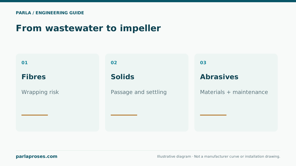
The main distinction between drainage and wastewater pumps lies in the material carried by the liquid and how the selected hydraulics handle it. Rainwater, groundwater seepage and basement accumulations can look similar while containing different amounts of grit, small debris and fibres. Domestic wastewater also requires assessment for soft solids, fibrous material and variable loads.
A description limited to clean or dirty water is therefore insufficient for selection. State approximate particle size, hardness, whether fibres are present, their concentration and the liquid temperature. A duty labelled drainage may contain enough abrasive grit to make a standard building drainage pump unsuitable. Likewise, a clear-looking liquid may require different materials because of its chemical composition.
Free passage alone does not describe blockage behaviour
The catalogue solids-passage value describes a defined geometric capacity of the particular model. A long cloth, hair or string cannot be characterised by particle diameter alone. Fibres can wrap around the impeller and adjacent surfaces, while material accumulated at the inlet can restrict flow before reaching the pump. Assess impeller type, inlet opening and operating conditions together.
Semi-open, channel and vortex impellers are considered for different duties. A vortex impeller should not be treated as a grinder; where size reduction is needed, assess a product and application intended for that purpose. Standard and vortex versions within one family may differ in both free passage and performance. Choosing the family name does not make every variant suitable.
| Observation | Feature to check | Selection implication |
|---|---|---|
| Small, occasional solids | Free passage and inlet arrangement | Verify the drainage variant’s limits |
| Wastewater containing fibres and cloth | Hydraulics and blockage management | Do not decide on passage size alone |
| High grit or abrasive loading | Wear materials and maintenance arrangement | Reassess suitability of a standard unit |
| Narrow sump or varying level | Float movement and stop level | Installation matters alongside hydraulics |
Worked example: include water arriving during emptying
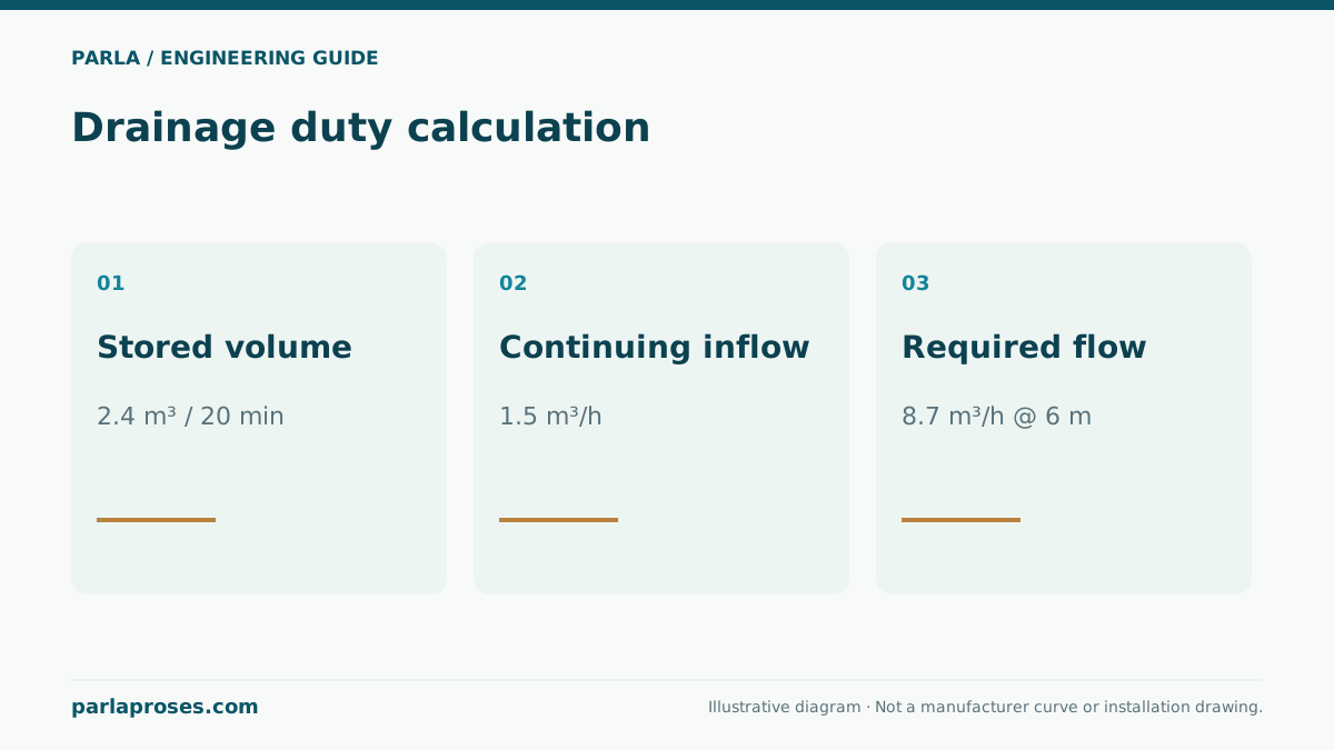
In an illustrative drainage scenario, assume an initial water volume of 2.4 m³ must be removed in 20 minutes. During that time, 1.5 m³/h continues to enter the sump. Dividing only the initial volume by the available time gives 2.4 / (20/60) = 7.2 m³/h. That is the required net rate of volume reduction, not the total pump flow.
The pump must also remove the continuing inflow, so its required flow is 7.2 + 1.5 = 8.7 m³/h. During the 20 minutes, 0.5 m³ of new water enters and the pump moves 2.9 m³ in total. The check is 8.7 × (20/60) = 2.9 m³. This assumes constant inflow and pump flow; varying rainfall or changing head requires assessment over time.
| Quantity | Calculation or assumption | Result |
|---|---|---|
| Initial volume | Accumulated water to be removed | 2.4 m³ |
| Target time | 20 / 60 hours | 0.333 hours |
| Net removal flow | 2.4 / (20/60) | 7.2 m³/h |
| Pump flow including inflow | 7.2 + 1.5 | 8.7 m³/h |
| Example total head | 4 m static + assumed 2 m line loss | 6 m; to be verified at this flow |
Hose losses and elevation change emptying time
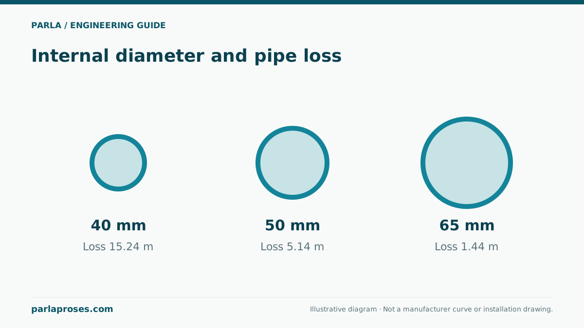
The example’s 6 m comprises 4 m of static elevation difference and an assumed 2 m of pipe, hose and fitting losses at 8.7 m³/h. It is not a site measurement. Calculate actual losses using diameter, length, elbows, check valve and outlet conditions. A folded hose or narrow connection can reduce delivered flow. As the water surface falls during emptying, static head can increase as well.
If the selected pump delivers only 8 m³/h in the actual line, with the same constant inflow of 1.5 m³/h, emptying takes 2.4 / (8 − 1.5) = 0.369 hours, or approximately 22.2 minutes. This illustrates why pipework and the duty point should be checked before increasing motor size. A low flow rate is not always caused by insufficient motor power.
Complete the decision with installation and level control
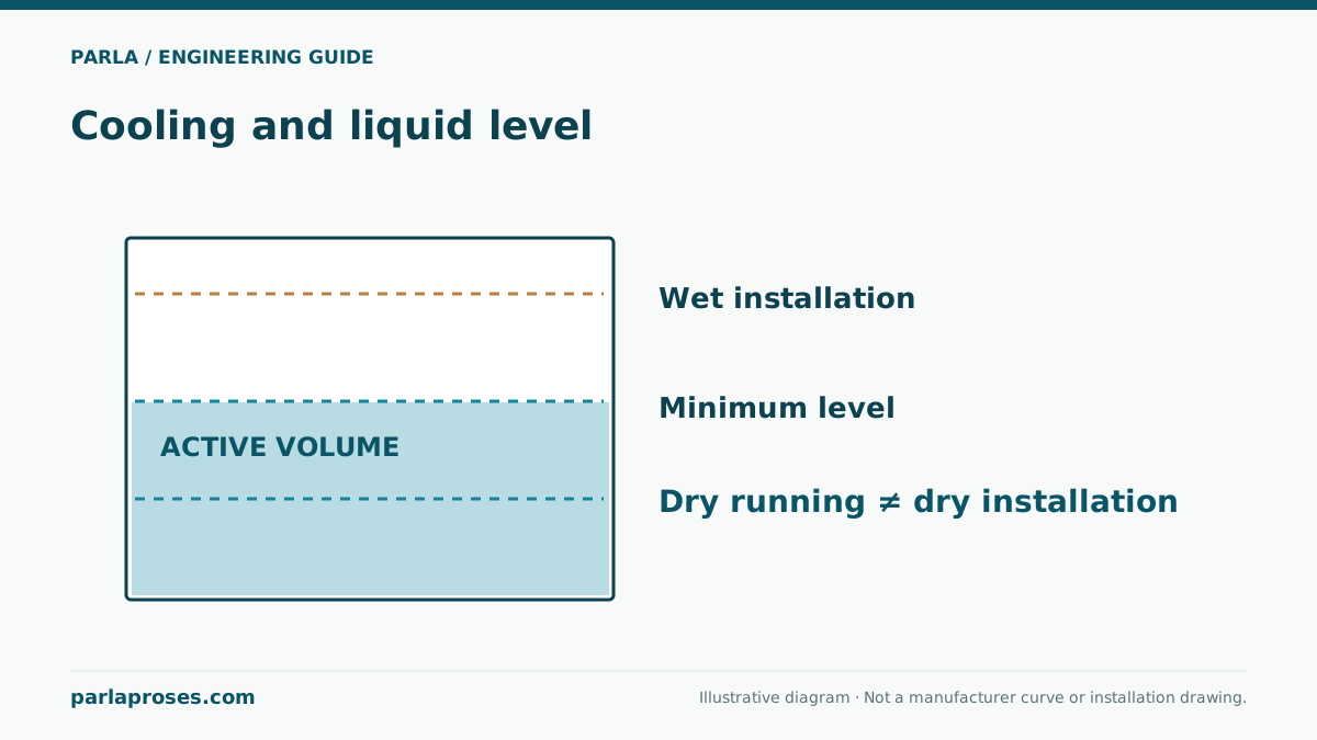
For portable duties, provide stable positioning, keep the inlet from becoming buried in sediment and maintain the hose’s open cross-section. In a permanent sump, allow enough room for the float switch to move without catching on walls or pipes. Set the stop level to satisfy minimum water-level and cooling requirements. The presence of thermal protection does not imply permission to run dry.
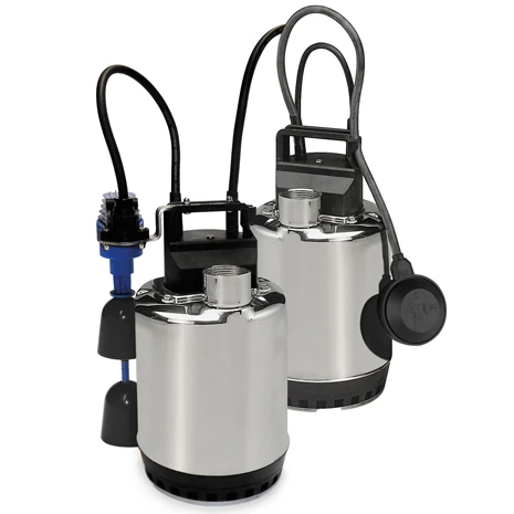
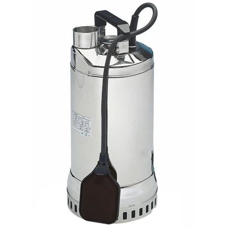
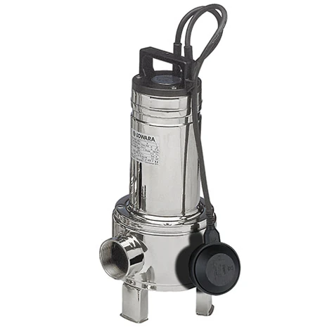
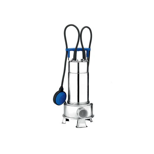
For product research, drainage families such as DOC and DIWA, and options for solids-bearing water such as DOMO or RIGHT, can provide starting points. None is approved here for the example duty. Include the water description, target time, inflow, pipe dimensions, electrical supply and sump dimensions in the quotation request. During commissioning, measure the actual level reduction to check the expected emptying time.
Frequently asked questions
Can a drainage pump handle domestic wastewater?+
Only when the liquid and solids conditions are permitted for the selected model. The drainage label alone does not establish suitability for domestic wastewater; assess fibrous loading, the impeller and manufacturer application limits.
Does a vortex impeller shred cloth?+
Grinding is not the primary function of a vortex impeller. Assess cloth and fibres separately. A system requiring size reduction needs a product and pipework design intended for that duty.
Why was 7.2 m³/h insufficient for 2.4 m³ of water?+
Because inflow continues at 1.5 m³/h in the example. The pump moves both the initial volume and new water, requiring a total flow of 8.7 m³/h to meet the 20-minute target.
Can catalogue maximum flow be used to calculate emptying time?+
It cannot directly replace actual line flow. Read the pump curve together with total head and use the flow available at the relevant water levels and pipework conditions.
Apply this assessment to your project.
Share your operating conditions, existing equipment and objective. Let’s assess product selection together with the technical documents.