Wastewater and Drainage
Dry running and cooling in submersible pumps: setting the level limits
A practical guide to stop level, motor cooling and level sensors in submersible wastewater pumps.
Illustrative engineering scenario · Assumptions are stated in the text.
AT A GLANCE
- Set stop level against the selected model’s minimum submergence and cooling requirements.
- Complete volume and cycle calculations with inflow, overflow storage and permitted starts.
- Accept level thresholds and fault scenarios through measured site tests.
Distinguish dry running from a brief loss of suction
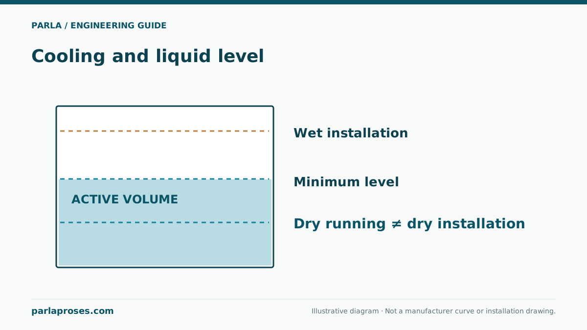
Submergence does not mean every pump can run safely at any water level. The circulation of liquid around the motor, the selected model’s minimum submergence for continuous duty, the impeller’s air ingestion limit and dry-run protection are separate matters. A float switch, electrode or pressure sensor does not change those limits. Establish the exact model, installation and manufacturer minimum level first. Liquid temperature and motor load also affect cooling. An option for dry installation under defined conditions must not be read as permission to run without liquid in a wet well.
At a low level the inlet may entrain air and lose flow while still drawing electrical power. Once exposed completely, seals or motor may suffer damage. Thermal protection is a last defence, not the normal stopping method.
Example sump: active volume and stop level are linked
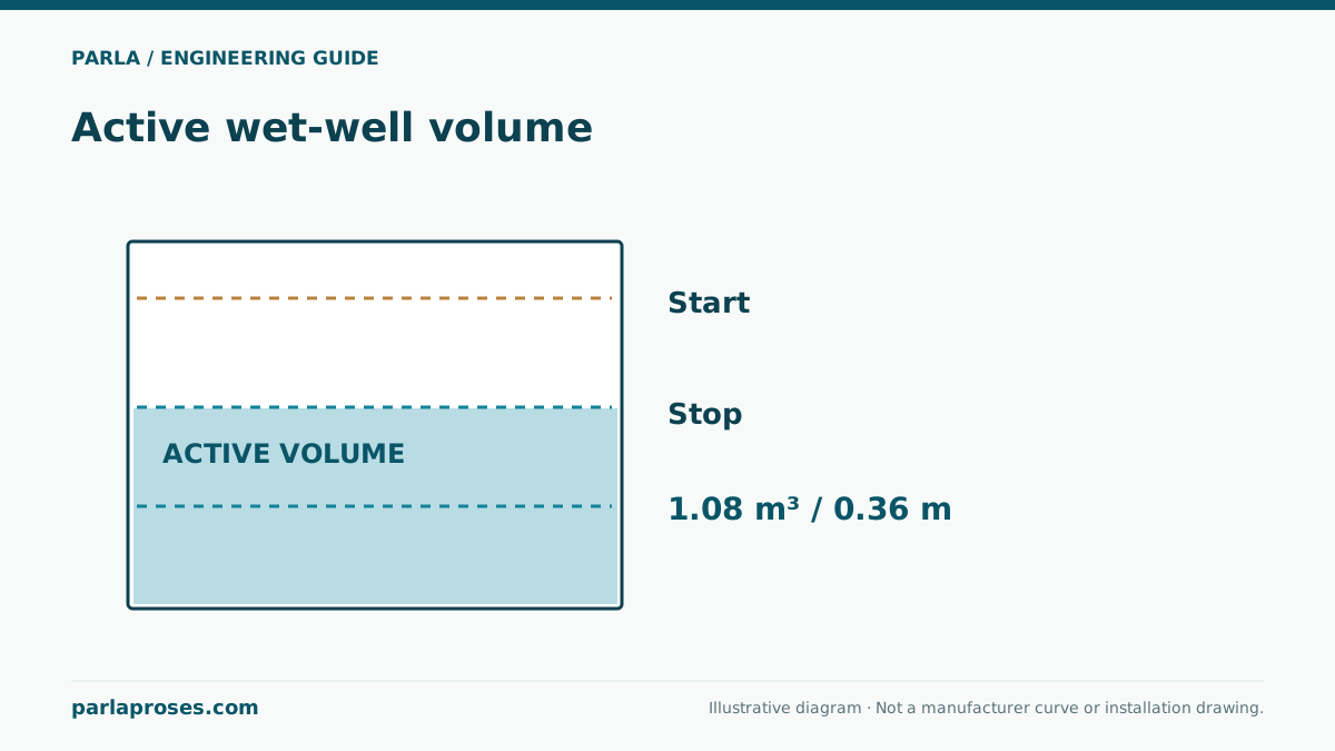
Suppose an illustrative sump has an internal plan of 1.4 m × 1.2 m, or 1.68 m². A 0.30 m difference between start and stop levels yields about 1.68 × 0.30 = 0.504 m³ of active volume. At an illustrative net discharge of 18 m³/h with no inflow, a cycle would run for 0.504 / 18 hours, or 1.68 minutes. Inflow extends the time, and pump delivery may change with water level. This arithmetic proves neither permitted starts per hour nor sufficient motor cooling.
Moving the stop level lower appears to increase volume but cannot violate the model’s minimum level. Raising the start level reduces overflow storage. Check start frequency, minimum submergence, high-level alarm and storage allowance together for the actual geometry.
| Item | Calculation / check | Why it matters |
|---|---|---|
| Sump area | 1.4 × 1.2 = 1.68 m² | Converts level span to volume |
| Active volume | 1.68 × 0.30 = 0.504 m³ | First input to cycle time |
| Idealised run time | 0.504 / 18 × 60 = 1.68 min | Assumes no inflow and constant pump flow |
| Stop level | Compare with manufacturer minimum | Cooling and inlet protection |
Consider two independent low-level protections
The normal level sensor controls cycling. A separate low-level interlock can be designed to stop the pump if a sensor sticks or communications fail. The need for this depends on a failure analysis and the selected control architecture. Do not position alarm thresholds arbitrarily; document the operator alarm and the energy shutdown logic. Air pressure, electrodes and ultrasonic sensing respond differently to wastewater foam and sediment. Use hysteresis to avoid rapid cycles caused by level fluctuations. Set standby-pump start and high-level points separately.
Record the actual cycle during commissioning
Before automatic operation, measure the real sump base level, pump position and sensor mounting. As water crosses each threshold, record pump status, current, flow, alarm and surface vortex behaviour. Test normal stop, sensor fault and high level safely with controlled clean-water supply where suitable; apply confined-space and personal protection procedures for wastewater wells. If the illustrative 1.68-minute cycle differs from measurements, revisit level span, actual pump delivery and inflow. Never test below the approved minimum level for the model. Record thresholds and sign-off in the acceptance document.
Link operating symptoms to root causes
Repeated thermal trips do not necessarily indicate a failed motor. Investigate inlet blockage, excessive drawdown, line valve position, phase sequence and voltage as well. Reviewing stop times, level trends, sump observations and current on one time axis reduces speculative replacement. Check float movement, cable entry and sealing during planned maintenance. If dry running is suspected, inspect according to the model manual before continuing service.
Frequently asked questions
Does thermal protection make dry running safe?+
No. Protection may limit damage but does not replace normal control that keeps liquid level and motor cooling within permitted conditions.
Can I set the stop level at the pump inlet?+
Not without checking the model and installation manual’s minimum level, air ingestion and motor cooling. Minimum level is often more than inlet elevation.
Is the example 0.30 m level span sufficient?+
It only yields 0.504 m³ of active volume. Permitted starts, real inflow, overflow storage and minimum water level require separate checks.
Does pump flow remain constant as the sump empties?+
Total head can change with water level. Check the example’s constant-flow assumption against the pump curve and measured cycle.
Apply this assessment to your project.
Share your operating conditions, existing equipment and objective. Let’s assess product selection together with the technical documents.