Wastewater and Drainage
Active volume and level selection for wastewater lift stations
Size the wet well using actual pump flow, permitted starts, minimum water level and the overflow scenario together.
Illustrative engineering scenario · Assumptions are stated in the text.
AT A GLANCE
- Calculate active volume, minimum submergence volume and emergency storage as separate functions.
- Use actual duty-point flow and a verified start limit in Q × T / 4.
- Combine the calculated level interval with minimum water level and the control scenario.
Separate total wet-well volume from active volume
Requesting a single lift-station volume combines several different functions. Active volume is the water volume used between the normal pump start and stop levels. The volume below it helps provide the required submergence and inlet conditions. The volume above it relates to the high-level alarm, standby pump start and the emergency scenarios defined by the operator.
The active-volume calculation does not by itself determine the complete civil structure. Guide rails, pipework, pump removal space, floor geometry and inlet-pipe elevation also need assessment. An oversized wet well that unnecessarily lengthens normal retention time is not automatically suitable; solids accumulation and wastewater retention need operational consideration.
Use model-specific start limits and duty-point flow
In a simple fixed-speed, single-pump arrangement controlled between two levels, the pump remains off while the well fills. It starts at the upper level and lowers the water level by pumping faster than the incoming flow. Pump flow Q is not the catalogue maximum: it is the flow delivered at the relevant system head. Inflow q may vary with time.
For 0 < q < Q, filling time is V/q and drawdown time is V/(Q − q). Their sum is one cycle. In this simplified model, the shortest cycle occurs at q = Q/2, giving V = Q × T / 4. Using Q in m³/s and T in seconds gives V in m³. Permitted starts per hour depend on the motor, controls and application; there is no universal limit for all submersible pumps.
Worked example: 1.08 m³ active volume for a 12 L/s pump
Assume a hypothetical project has a pump duty-point flow of 12 L/s and an assumed calculation limit of 10 starts per hour. This limit is only an example assumption, not an approved value for a particular Flygt model or data from a Parla Proses project. The minimum interval between successive starts is 3,600 / 10 = 360 seconds.
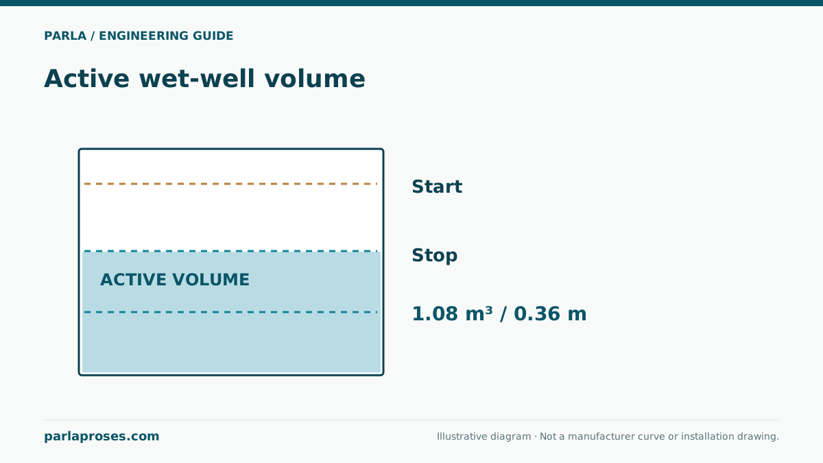
With Q = 0.012 m³/s, active volume is 0.012 × 360 / 4 = 1.08 m³. At the most frequent starting condition, inflow is 6 L/s, so filling takes 1.08 / 0.006 = 180 seconds and drawdown takes 1.08 / (0.012 − 0.006) = 180 seconds. The total cycle is therefore 360 seconds. If pump flow changes with water level in the actual well, check performance across the level interval.
| Calculation input | Value | Interpretation |
|---|---|---|
| Pump flow Q | 12 L/s = 0.012 m³/s | Assumed at the duty point |
| Starts per hour | 10 | Requires model-specific verification |
| Cycle time T | 360 seconds | Sum of filling and drawdown |
| Active volume V | 1.08 m³ | Excludes emergency storage |
| Net horizontal area A | 3.00 m² | Assumed constant within this interval |
| Level difference Δh | 0.36 m | 1.08 / 3.00; not the absolute stop elevation |
Tie the level sequence to operating scenarios
Do not measure the calculated 0.36 m interval directly from the floor. First establish the lowest permitted level at which the pump may stop. Position the active interval above that elevation to obtain the normal start level. Where the well cross-section varies, use the actual volume within each elevation interval instead of multiplying by one constant area; account for equipment displacement as well.
Clearly define the high-level alarm, the second-pump start level where applicable, and the overflow limit. Check sensor range and fluctuations, free movement of float switches, and turbulence from the inlet. Emergency storage is a separate assessment of the incoming water accumulated during the selected failure and response period. Active volume should not be assumed to provide this function automatically.
Reassess the control logic for two pumps and variable speed
Alternating two pumps does not justify arbitrarily adding a factor of two to the single-pump formula. Assess each motor’s actual starts using the alternation sequence, simultaneous operation and failure scenarios. The combined flow of parallel pumps may not be exactly twice the single-pump flow because the shared system curve changes the duty point.
With variable speed, level control changes the cycling behaviour. Consider minimum speed, minimum run time and the stopping strategy together with solids management in the well and rising main. During commissioning, record starts and stops at several inflow loads; verify actual cycle time, high-level alarm response and standby-pump behaviour. Record setting changes with their dates and reasons in the operating file.
Frequently asked questions
Can 10 starts per hour be used for every pump?+
No. It is an assumption for the worked example. Verify permitted starts against the selected pump and motor documentation, electrical controls and application conditions.
Is 1.08 m³ the total wet-well volume?+
No. It is only the example’s active volume between start and stop levels. Lower submergence volume, equipment layout and required upper storage are assessed separately.
What happens when inflow equals pump flow?+
Under the ideal constant-flow assumption, the running pump cannot lower the level. If inflow exceeds pump flow, the level rises. Check peak inflow and backup capacity separately from the cycling calculation.
Does increasing the level interval always improve operation?+
A wider interval may reduce starts but also changes retention time, available upper storage and inlet conditions. Verify any new setting against minimum water level and alarm stages.
Apply this assessment to your project.
Share your operating conditions, existing equipment and objective. Let’s assess product selection together with the technical documents.