Pump engineering
Pumps in parallel or series? Decide with the curves
Two pumps do not simply double flow or head. Calculate the actual duty point where their combined curve meets the system curve.
Illustrative engineering scenario · Assumptions are stated in the text.
AT A GLANCE
- Add flows at equal head for parallel; add heads at equal flow for series.
- Always intersect the combined curve with the system curve again.
- Check simultaneous suction loss, motor range and allowable pressures.
What determines the arrangement?
In parallel, pumps operate between common suction and delivery headers. Add each pump’s flow at the same differential head; for identical machines the combined curve is Q_total(H) = 2Q_single(H). In series, the outlet of the first feeds the inlet of the second. Add differential heads at the same flow: H_total(Q) = H₁(Q) + H₂(Q). Neither arrangement is modelled by arbitrarily doubling the flow and head at one selected single-pump duty point. Operation changes where the new combined curve intersects the system curve.
Parallel operation is often considered for varying flow and staged capacity; series operation for higher pressure at a defined flow. Existing pipe diameter, low-level suction condition, curve shape, motor range and controls remain prerequisites. Do not mistake a true standby N+1 pump for a second pump counted in simultaneous capacity.
Construct illustrative curves in consistent units
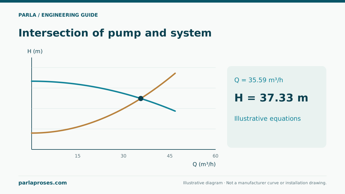
In this illustrative example, which is not an actual product curve, assume one pump H_p = 60 − 0.10Q² and the system H_s = 20 + 0.15Q², with H in metres and Q in m³/h. Static head is 20 m; the quadratic term aggregates this example’s friction and local losses. For one pump, 60 − 0.10Q² = 20 + 0.15Q² gives Q² = 160, Q ≈ 12.65 m³/h and H ≈ 44.0 m. This model does not establish that a real curve is parabolic: use catalogue curves, differing pump efficiencies and section-by-section pipe losses for actual selection.
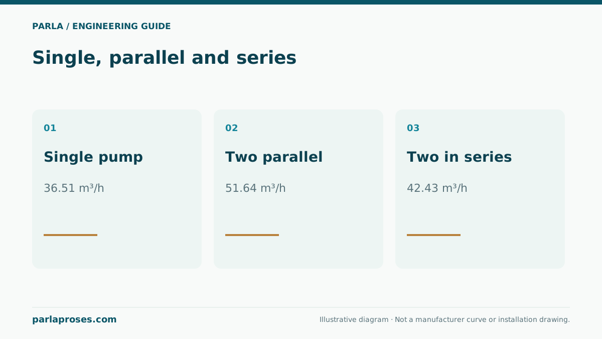
For two equal pumps in parallel, each handles half the total flow at the same head, hence H_parallel(Q) = 60 − 0.10(Q/2)² = 60 − 0.025Q². Intersection gives Q² = 40/0.175 ≈ 228.57, total Q ≈ 15.12 m³/h and H ≈ 54.29 m. Each pump delivers about 7.56 m³/h. Two in series give H_series(Q) = 120 − 0.20Q². Intersection yields Q² = 100/0.35 ≈ 285.71, Q ≈ 16.90 m³/h and H ≈ 62.86 m.
| Arrangement | Total flow | System head | Selection implication |
|---|---|---|---|
| One pump | 12.65 m³/h | 44.0 m | Reference duty point |
| Two parallel | 15.12 m³/h | 54.29 m | Flow gain 19.5%, not double |
| Two in series | 16.90 m³/h | 62.86 m | Check second-casing inlet pressure |
Recalculate when one pump stops
If one of two parallel pumps stops, the illustrative point returns to the single-pump value, roughly 12.65 m³/h. In practice, check-valve leakage, manifold losses and speed control change that value. If one series pump is unavailable, one-pump behaviour cannot be assumed without assessing bypass, check valves and allowable pressures of both casings. A stopped machine may add resistance. Show normal, fault and maintenance cases separately in the operating philosophy.
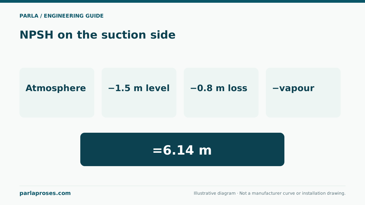
If parallel pumps share a suction header, that section carries total flow. Its loss may increase approximately with the square of flow and available NPSH can shrink. In series, the second pump sees elevated inlet pressure; keep the casing, seal, flange, pipe and pressure ratings within limits under every condition. Check the first pump’s suction conditions independently.
Selection and commissioning checks
Request single and combined manufacturer curves for the same liquid, speed and impeller diameter. Assess flow range, preferred operating region, motor power, minimum continuous flow and NPSHr for each case. Start and stop thresholds in staged control should limit cycling and prevent unstable speed commands between machines. For series operation, design staged starting alongside minimum and maximum pressure at the second pump inlet.
As an illustrative application, a washing line with variable demand will not automatically get twice the water when two pumps run in parallel. Under the assumed curves, the gain is only about 19.5%. An operator observing this should first verify common-pipe losses and actual curves, rather than declaring a pump fault. This is a worked scenario, not a completed Parla customer project.
Frequently asked questions
Why does parallel connection of identical pumps not double flow?+
Increased total flow raises loss in shared piping. The combined curve meets the system curve at higher head, so each pump does not retain its original single-machine flow.
Do series pumps always provide twice the pressure?+
Only differential heads at the same flow are added. The new duty flow changes; system pressure also depends on static head, losses and inlet pressure.
Is the NPSH check identical for one and two parallel pumps?+
No. Recalculate common suction-header loss at combined flow, and compare each pump’s NPSHr at its own flow.
Can a standby pump count toward simultaneous capacity?+
Only if the operating design permits simultaneous use and verifies that case against all limits. N+1 redundancy is meant to retain capacity after a failure.
Apply this assessment to your project.
Share your operating conditions, existing equipment and objective. Let’s assess product selection together with the technical documents.