Product selection guides
Lowara e-SV selection: data and example for a vertical multistage pump
Do not select from the e-SV family using a single range maximum. Bring flow, system head, NPSH, materials and controls together in a worked example.
Illustrative engineering scenario · Assumptions are stated in the text.
AT A GLANCE
- Do not treat family maxima as one simultaneous duty point.
- Calculate the system Q-H point before using the exact variant curve.
- Verify NPSH, pressure rating, chemistry and variable demand separately.
Record the application boundaries first
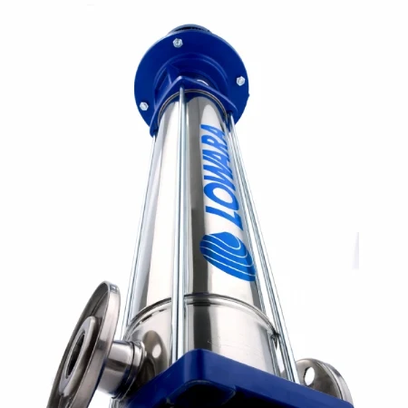
The Lowara e-SV is a non-self-priming vertical multistage family according to Xylem. The manufacturer gives envelope figures up to 160 m³/h and 330 m across the family. Those maxima do not represent a simultaneous duty point of one model. To select a series, consider required flow, total differential head at that flow, liquid properties and allowable operating range together. Xylem identifies clean water without suspended solids and other liquids depending on variant; confirm materials and elastomer compatibility for chemical mixtures.
A useful enquiry needs more than “a 60-metre pump”: provide flow, minimum and maximum inlet pressure, temperature, density, viscosity, mineral or glycol content, duty cycle and electrical supply. Verify operating pressure, liquid temperature and connection against the exact hydraulic and casing variant. A high casing pressure class does not mean every component permits the same pressure at every temperature.
Establish the 18 m³/h system duty
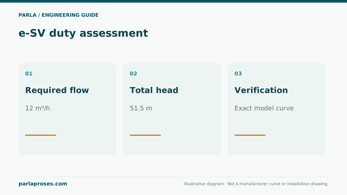
In an illustrative pressure-boosting case, assume target flow of 18 m³/h, static lift of 12 m, residual pressure required at the outlet of 3 bar, and line plus equipment loss of 16 m at design flow. For water near 1000 kg/m³, 3 bar ≈ 30.6 m water head. Total required differential head is H = 12 + 30.6 + 16 = 58.6 m. The point at 18 m³/h and 58.6 m corresponds to approximately 18 × 58.6 / 367 ≈ 2.87 kW hydraulic power; 367 is the water-unit conversion divisor for kW and m³/h. At an assumed aggregate efficiency of 60%, electrical input would be about 4.79 kW, but a motor must not be specified from that coarse estimate.
Plot 18 m³/h and 58.6 m on the manufacturer curve for a suitable stage, impeller and speed variant. Read the exact code’s curve, position around best efficiency, permitted minimum and maximum flow, power curve and NPSHr. Check that delivery and shutoff pressure including inlet pressure remain within pipe ratings, and confirm suction at the lowest tank level. These numbers are illustrative and do not promise a duty from any e-SV model.
| Term | Example value | Validation |
|---|---|---|
| Static lift | 12 m | Measure at limiting liquid levels |
| Residual outlet pressure | 3 bar ≈ 30.6 m | Define gauge location and density |
| Piping and equipment loss | 16 m at 18 m³/h | Include fouled-filter case |
| Total differential head | 58.6 m at 18 m³/h | Mark on exact e-SV model curve |
Show varying demand in pressure boosting
Selection at one point is only the start. Define low night use, normal daytime demand and plausible simultaneous peak demand separately. A single large pump running continuously at very low flow can cycle, heat or operate inefficiently. Consider variable speed, multiple pumps or an appropriate pressure vessel; check the control range against the manufacturer’s minimum and maximum speeds. Recalculate common suction and delivery-header losses for each stage of a parallel set.
Illustrative field scenario: upper-floor pressure fluctuates at night. Instead of simply upsizing the pump, log night flow, sensor location, pressure-vessel precharge and start-stop thresholds. A valve or head loss at the sensor location can change the measured target. This is neither a real Parla customer project nor a verified site saving; it illustrates how to separate possible causes using data.
Complete the model code with final checks
Measure installation and service clearances for the vertical arrangement. Arrange the base, pipe supports and thermal expansion according to manufacturer instructions; pump flanges should not carry pipe weight. Confirm seal, elastomer and metal selections for liquid temperature and chemistry with the manufacturer. Tank level and suction pressure enter the NPSHa calculation; filling and venting can be critical for the non-self-priming design. Keep the exact product code, performance curve, motor and power information together with the enquiry conditions.
Seeing family-envelope numbers of 160 m³/h and 330 m in a search description is not installation approval. Confirm process pressure, water quality and any regulatory certification requirement for the exact variant.
Frequently asked questions
Does an e-SV deliver 330 m at 160 m³/h?+
They are separate range-envelope maxima, not a simultaneous duty point. Read head at the required flow from the curve of the exact product code.
Is the motor size fixed by the 18 m³/h, 58.6 m example?+
No. Hydraulic power of 2.87 kW and assumed input of 4.79 kW only illustrate a calculation. Verify actual efficiency, maximum shaft power across the curve and service factor using manufacturer data.
Is a pressure vessel or speed control mandatory?+
It depends on the application and control philosophy. Assess variable demand, allowable starts, minimum flow and water hammer together.
Can a standard e-SV be selected for a chemical liquid?+
Do not approve it without composition, temperature, concentration and elastomer/seal compatibility. Determine the appropriate variant against manufacturer material and application data.
Apply this assessment to your project.
Share your operating conditions, existing equipment and objective. Let’s assess product selection together with the technical documents.