Product selection guides
Ebara MATRIX selection: when is a horizontal multistage pump suitable?
Evaluate the MATRIX family at a specific flow and head, not from envelope limits. Use an annotated water-transfer calculation and selection table.
Illustrative engineering scenario · Assumptions are stated in the text.
AT A GLANCE
- Use the exact model curve rather than the MATRIX family envelope.
- In the 6 m³/h example, 36 m combines elevation, residual pressure and losses.
- Check NPSH and inlet pressure separately, and their combined impact on discharge pressure.
Do not mistake the family envelope for one selected model
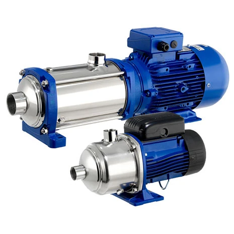
Ebara’s MATRIX horizontal multistage family is listed with envelope figures up to 27 m³/h and 97 m head. These maxima are not one simultaneous operating point of one pump. Selection means finding a hydraulic curve and corresponding number of stages that meet head at the required flow. Separately confirm motor suitability for supply, environment and duty cycle.
A horizontal configuration may fit a low mechanical room, but measure floor footprint and suction geometry. Existing product data gives a maximum working pressure of 10 bar for MATRIX; verify actual permissible conditions for the selected variant and liquid temperature. Establish liquid cleanliness, temperature, chemistry and any drinking-water or food-contact certification requirements before installation.
A 6 m³/h water transfer example
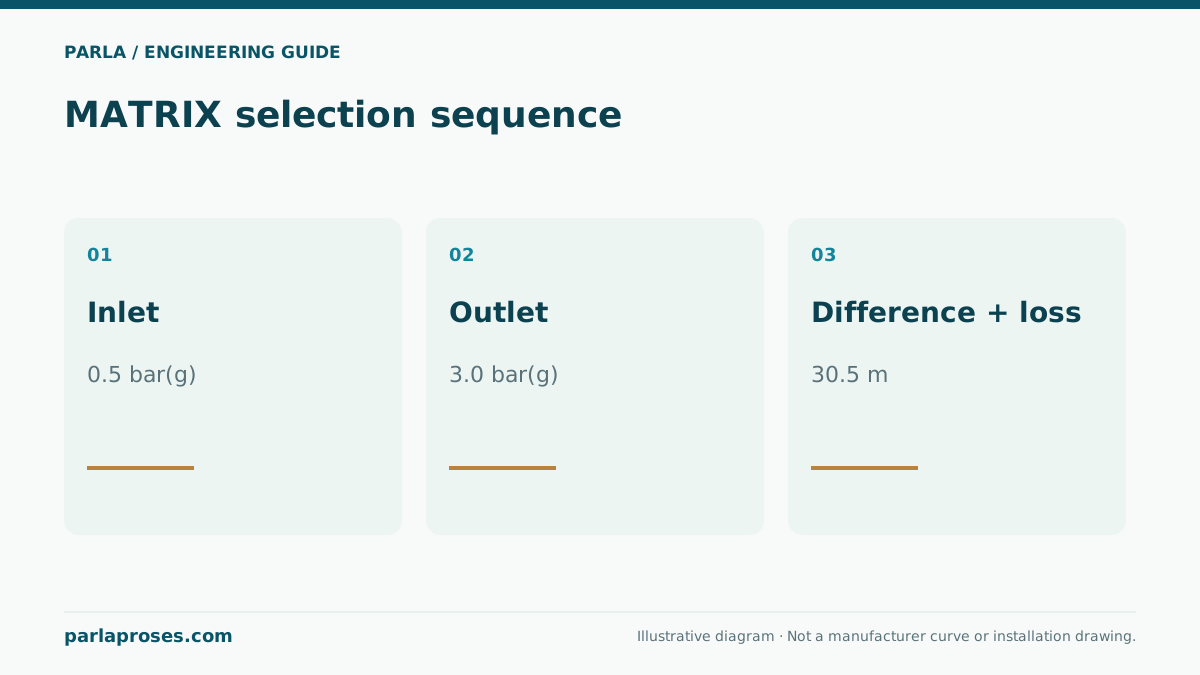
Assume a clean-water transfer from a lower open tank to a pressurised point upstairs. The illustrative target flow is 6 m³/h, elevation between tank surface and use point 9 m, residual gauge pressure at that point 2 bar, and friction plus equipment loss at design flow 6.6 m. At approximate water density of 1000 kg/m³, 2 bar corresponds to 200000/(1000 × 9.81) ≈ 20.4 m of head. Required differential head is therefore H ≈ 9 + 20.4 + 6.6 = 36.0 m. The target duty is 6 m³/h at 36 m.
Hydraulic power is roughly P_h = ρgQH = 1000 × 9.81 × (6/3600) × 36 ≈ 0.589 kW. At an assumed 50% aggregate efficiency, input power is 1.18 kW. This does not determine the motor nameplate. Check actual efficiency and shaft power across the operating range on the manufacturer curve for the exact code; different stage counts around the same point can give different efficiency and NPSHr. The site and figures are illustrative, not a real Parla application.
| Input | Value | Field validation |
|---|---|---|
| Target flow | 6 m³/h | Simultaneous demand |
| Elevation | 9 m | Lowest tank level |
| Residual pressure | 2 bar ≈ 20.4 m | Required at use point |
| Pipe and equipment loss | 6.6 m | At design flow, include fouled filter if present |
| Total | 36.0 m | Read with 6 m³/h on model curve |
Assess inlet pressure and suction safety together
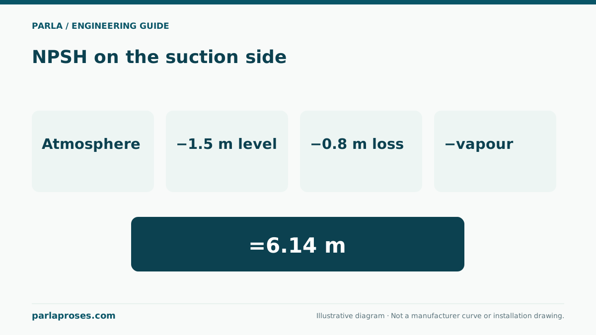
Do not assume self-priming when the tank sits below the pump; use the exact model’s installation instructions. Calculate NPSHa with the lowest tank level, suction pipe losses, water temperature and local atmospheric pressure. Compare with NPSHr at the same flow using the appropriate margin. Include filling, venting and dry-run prevention in the commissioning plan.
When the tank is above the pump, positive inlet gauge pressure exists. Do not read maximum casing working pressure as the pump’s differential pressure alone: maximum possible discharge pressure includes inlet pressure and the pump’s relevant limiting condition. Check pipe, connection, valve and seal ratings for elevated temperature, shutoff and transients.
Separate a fault story with measurements
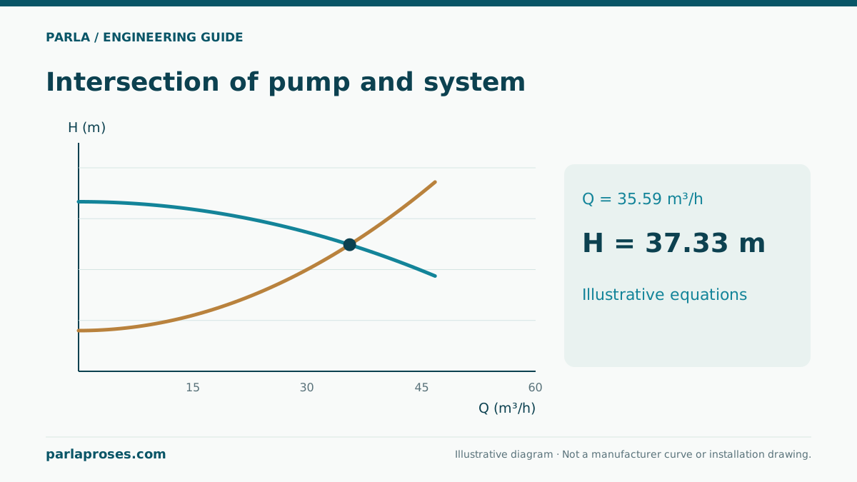
In a hypothetical operating scenario, an expected 6 m³/h line delivers only 4 m³/h at day’s end. Before declaring a pump failure or adding stages, record suction and discharge pressure simultaneously, measure filter differential pressure, and check tank level and line valves. A fouled filter increases loss and shifts the duty point along the system curve toward lower flow. Compare before-and-after cleaning measurements at the same speed to test that explanation.
MATRIX selection is not just exceeding the stated 36 m point: approve the exact model curve, operating region, NPSHr, motor load, chemical compatibility and installation instructions together. If demand varies, specify low-flow cycling behaviour and control method. This fault story is a hypothetical teaching scenario, not a Parla site reference.
Frequently asked questions
Do 27 m³/h and 97 m apply at one MATRIX duty point?+
No. Separate maxima of the family envelope do not define a flow and head point on one exact model curve.
Is 1.18 kW the motor rating in the example?+
No. It estimates input at an assumed 50% total efficiency. Select motor and shaft power from the exact manufacturer curve, supply and service limits.
How is a 10 bar limit interpreted with inlet pressure?+
Evaluate inlet pressure together with possible pump differential. At maximum temperature and limiting operation, check the selected variant’s casing, connection and seal limits.
What should be measured first when flow falls?+
Log flow, suction/discharge pressures, tank level and filter differential pressure at the same speed. Motor current alone cannot locate the fault.
Apply this assessment to your project.
Share your operating conditions, existing equipment and objective. Let’s assess product selection together with the technical documents.