Water supply and operation
Borehole pump selection: dynamic level, flow and motor
Well depth alone does not determine pump head. Build the duty point from pumping water level, delivery elevation, required pressure and actual pipe losses.
Illustrative engineering scenario · Assumptions are stated in the text.
AT A GLANCE
- Build the duty point from pumping water level; do not treat installation depth as total dynamic head.
- Verify well yield, seasonal levels and actual line losses at the required flow.
- Assess motor cooling, cabling and protection together with hydraulic selection.
Define well yield and duty flow first
Borehole pump selection should not begin with total well depth or motor power. First assess the required supply flow and whether the well can sustain it. Read the drilling record, casing inside diameter, screened intervals, static water level, pumping levels measured at different flows and recovery behaviour together. The static level measured before pumping is not interchangeable with the dynamic level during pumping. If water level continues falling during prolonged operation, a measurement from the first few minutes is not an adequate selection input.
When instantaneous demand exceeds sustainable well yield, a larger pump does not increase the water resource. Consider suitable storage, steadier abstraction and balancing demand over time. Water analysis, sand content and temperature are also required inputs: a hydraulically suitable model may be unsuitable in terms of materials or wear. Collecting these details on one enquiry form exposes the gaps in a selection based solely on well depth.
Example: total dynamic head of 103.6 metres
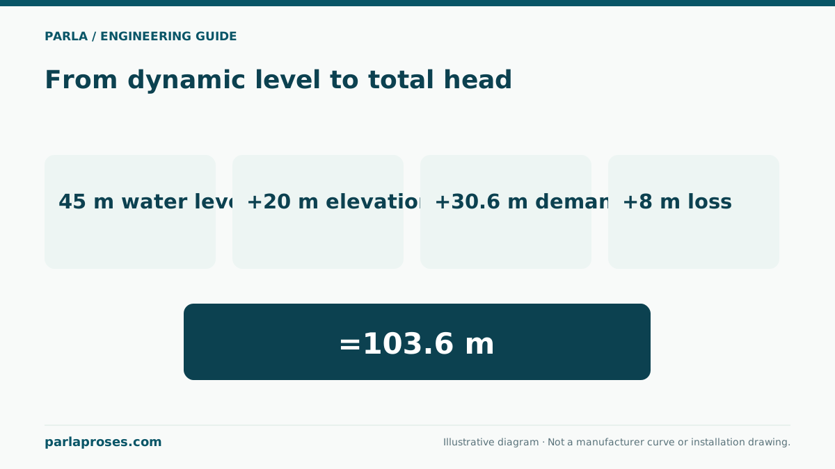
Consider an illustrative borehole application delivering 6 m³/h. Take ground level as the elevation datum. At this flow, assume a stable pumping water level 45 metres below ground and a delivery point 20 metres above ground. Required residual pressure at delivery is 3 bar(g), and the combined loss through all actual pipes and fittings at this flow is 8 metres. For water with density approximately 1,000 kg/m³, 3 bar corresponds to 30.6 metres of water head. The difference in endpoint velocity heads is neglected in this example.
Total dynamic head is H = 45 + 20 + 30.6 + 8 = 103.6 metres. The illustrative duty point is therefore 6 m³/h at 103.6 metres. Even if the pump is installed at 65 metres, do not replace 45 with 65 in this calculation. The water column above the pump inlet contributes inlet pressure; the net elevation lift is from the pumping water surface to the delivery point. Installation depth does, however, affect the actual rising-main length and therefore enters the friction-loss calculation indirectly.
| Input | Value | Meaning in the calculation |
|---|---|---|
| Pumping water level | −45 m | Operating level below ground, not the static level |
| Delivery elevation | +20 m | Geometric rise from water surface to delivery is 65 m |
| Residual delivery pressure | 3 bar(g) ≈ 30.6 m | Pressure to be retained at the delivery point |
| Pipe and local losses | 8 m | Total loss calculated at duty flow |
| Total dynamic head | 103.6 m | Check together with 6 m³/h on the pump curve |
| Pump installation depth | 65 m | 20 m below pumping level in this example; not total dynamic head |
Check the pump curve, power and motor together
Check the calculated duty point on the actual performance curve for the selected stage count. A catalogue family’s maximum flow and maximum head are not a simultaneously available duty point. Expected minimum and maximum pumping levels, changing delivery pressures and valve positions define the possible operating region. Assess efficiency, permitted flow range and power demand across that region.
In the example, hydraulic power from P = ρgQH is approximately 1,000 × 9.81 × (6 / 3,600) × 103.6 ≈ 1.69 kW. Assuming a combined pump-and-motor efficiency of 60% solely to demonstrate the calculation gives electrical input of approximately 1.69 / 0.60 = 2.82 kW. This does not directly select a motor nameplate rating. Select the motor from required pump shaft power, the entire operating region, compatible motor data and manufacturer conditions. Separately verify the electrical supply, actual cable route, voltage drop and protection arrangement.
Installation depth also involves cooling and maintenance
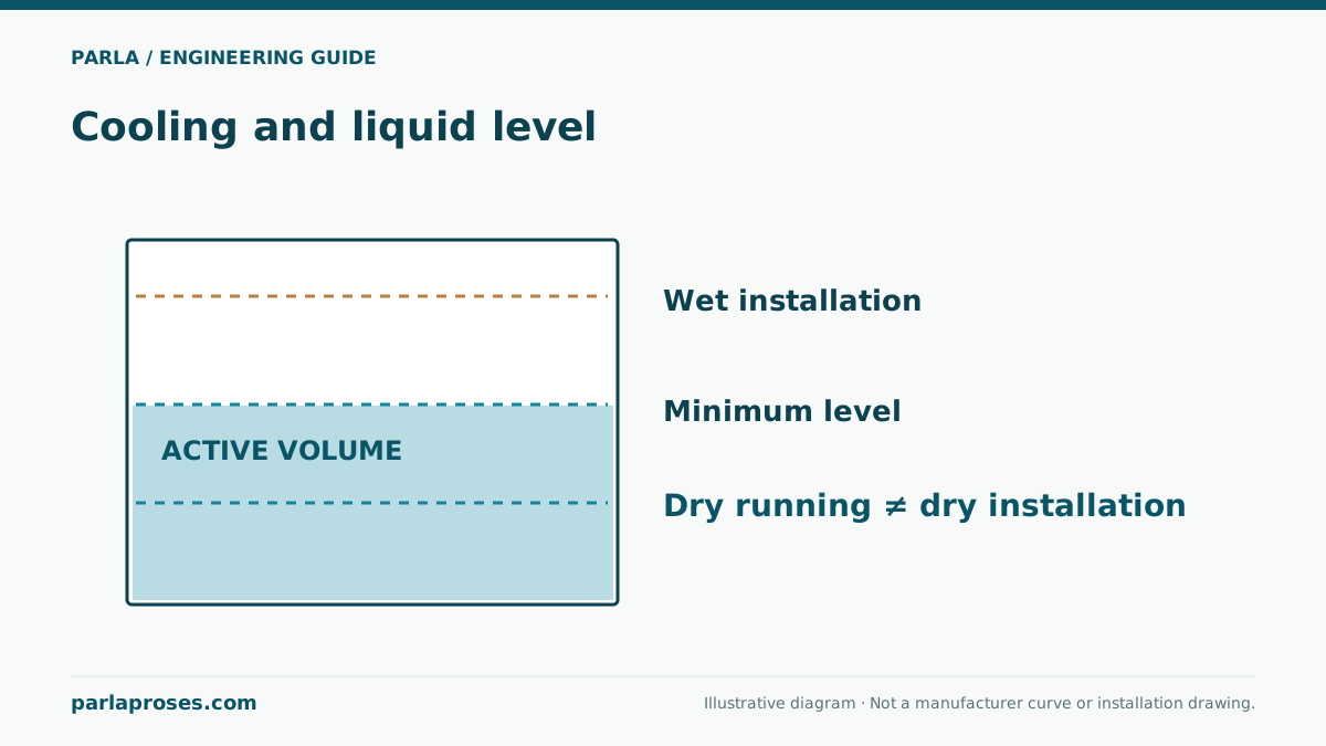
Submergence alone does not demonstrate adequate motor cooling. Review the water path around the motor, borehole diameter, screened intervals and the flow conditions required by the manufacturer. A cooling shroud may be needed in some installations; confirm the requirement with the manufacturer. Position relative to the well bottom, screened intervals and accumulated sand also follows well design and equipment instructions. Do not assume a universal bottom clearance or cooling velocity.
At commissioning, record flow, wellhead pressure, pumping water level, current and supply voltage together. Define the conditions that trigger low-level or dry-running protection and how restarting is managed. Compare pressures possible with closed valves or during stopping transients against pipe and connection ratings. Trends in these same measurements can later help distinguish changing well performance, pipe leakage and pump wear. Lowering the equipment and making electrical connections require competent personnel and suitable lifting and isolation arrangements.
Frequently asked questions
Is 65 metres of head enough for a pump installed at 65 metres?+
Installation depth cannot answer that question. In the example, pumping level, delivery elevation, residual pressure and losses total 103.6 metres. Selection must deliver that head at the required flow.
Can the pump be selected from static water level?+
Static level is initial information. The operating level depends on pumping flow and well behaviour. Selection requires pumping levels at relevant flows and assessment of seasonal variation.
Will a more powerful motor provide more water from the well?+
Not by itself. Flow is limited jointly by the pump curve, system and sustainable well yield. Excessive abstraction from an insufficient source can worsen drawdown; consider storage and the operating schedule.
Why might a cooling shroud be needed when the pump is submerged?+
Water movement around the motor depends on inlet location and well geometry. If water does not pass the motor adequately, required cooling may not be achieved. Verify shroud requirements using motor and well data.
Apply this assessment to your project.
Share your operating conditions, existing equipment and objective. Let’s assess product selection together with the technical documents.