Mixing and Process
Submersible mixer selection: tank geometry, flow path and suspension
Assess tank sections, sediment, inlet flow and maintenance access instead of choosing a mixer by motor rating alone.
Illustrative engineering scenario · Assumptions are stated in the text.
AT A GLANCE
- Define process objective and solids conditions before using tank volume.
- Check flow path and installation clearances at normal and minimum levels.
- Evaluate energy savings only while monitoring process quality and bottom accumulation.
Define the process objective first
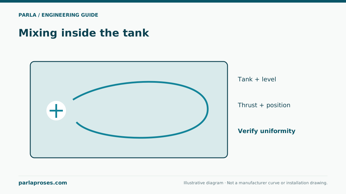
Mixing may aim to prevent settling, homogenise concentration or create circulation in a biological process zone. These are distinct objectives. Record solids to be suspended, settling behaviour, operating level range, vessel shape and inlet/outlet flows. If oxygen transfer is required, do not assume a submersible mixer alone performs that duty; evaluate aeration separately. Neither rated thrust nor motor power alone proves that all tank zones achieve the required flow. Walls, columns and pipes interrupt circulation. Complex vessels may require manufacturer layout support or suitable flow modelling.
Tank volume is only a first screening value
For illustration, take an equalisation tank 8 m long, 5 m wide and normally 3 m deep. The wet volume is 8 × 5 × 3 = 120 m³. At 2 m depth it becomes 80 m³, so a 1 m level change changes volume by 40 m³. The 120 m³ figure is not a direct formula for mixer count or power. Check propeller submergence, surface vortex and bottom clearance at low level; at high level check circulation in upper and distant corners.
Suppose the inlet is on a short side and the outlet opposite. Placing a mixer only near the outlet may create a short circuit; validate the angle against obstructions and manufacturer layout guidance.
| Input | Example value | Design effect |
|---|---|---|
| Plan dimensions | 8 × 5 = 40 m² | Check remote corners and return path |
| Normal volume | 40 × 3 = 120 m³ | Process and retention screening |
| Low-level volume | 40 × 2 = 80 m³ | Propeller submergence and bottom clearance |
| Obstructions | Columns, piping, inlet jet | Affects flow direction and dead zones |
Read the arrangement on drawings and on site
Compare propeller distances to walls, bottom and water surface with the manufacturer installation dimensions. The centre of a tank is not automatically the best circulation point. Show the returning flow path, inlet jet and pockets where sludge may collect. The guide rail or lifting arrangement must be accessible from the intended maintenance side. Route cables so they do not move into the propeller. With multiple mixers, choose orientations that do not cancel circulation and define operation across water levels.
Calculate energy against process demand
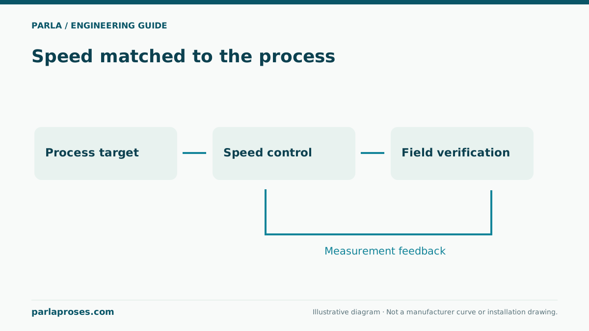
If an illustrative 2.2 kW input is used for 18 hours per day, daily energy is 2.2 × 18 = 39.6 kWh. Replace the nameplate assumption with measured electrical input. Reducing runtime by timer to 12 hours would theoretically save 13.2 kWh/day, but it is not an acceptable saving if settling or process quality deteriorates. Control linked to level, solids load or process phase needs measured validation. Record bottom accumulation and homogeneity as seasonal loads change.
Define evidence for commissioning
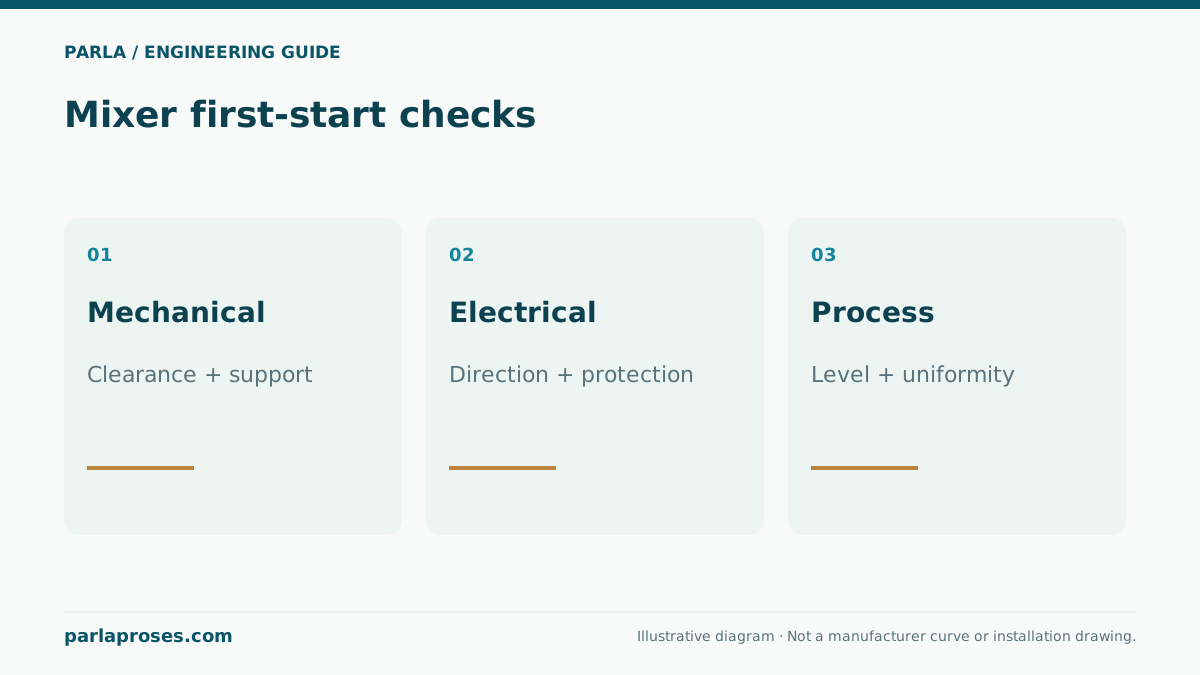
Check rotation, current, seal monitoring, vibration and lifting arrangement on first start. Observe surface vortices and dead zones at low and high levels without crossing safe access boundaries. An observation from one corner does not prove homogeneity. Depending on process, sample solids or relevant concentration from several locations. Sediment observations and energy meter readings establish a baseline for later comparison. Confirm the selected Flygt single-speed or adaptive model’s precise installation and application limits in its own data sheet.
Frequently asked questions
Can mixer quantity be calculated from tank volume alone?+
No. Volume is a starting input; geometry, obstructions, water level, solids and the process objective determine circulation. Review layout and selected model data together.
Is 12 hours of operation sufficient in the 2.2 kW example?+
It is an energy scenario only. Do not reduce operating hours without assessing bottom settlement and process variables.
Does a mixer replace an aerator?+
Circulation and oxygen transfer are different duties. Calculate oxygen demand and aeration capacity separately.
Why is the low water level important?+
Propeller submergence, clearances, vortex formation and cooling must remain within the selected model’s limits.
Apply this assessment to your project.
Share your operating conditions, existing equipment and objective. Let’s assess product selection together with the technical documents.