Maintenance and reliability
Pump vibration in maintenance planning: from measurement to action
Do not judge vibration from one number. Trend it at the same location with flow, speed, pressure and service history.
Illustrative engineering scenario · Assumptions are stated in the text.
AT A GLANCE
- Trend vibration at the same location and comparable duty alongside pressure and flow.
- An 80% rise is an investigation signal, not a universal shutdown threshold.
- Repeat measurements under comparable conditions after intervention.
Vibration is a symptom; the duty is context
Pump vibration can increase with a changed duty point, air ingress, cavitation, imbalance, coupling misalignment, loose connections, pipe loads or bearing faults. One overall reading does not identify the failed part. A trend of repeated measurements at the same position and orientation on the bearing housing, ideally with the same instrument and method, is more useful. Record flow, suction and discharge pressures, speed and valve status at measurement time.
Conditions shift with frequency on a variable-speed pump; do not compare 35 Hz against 50 Hz without context. A neighbouring machine can transmit vibration even when the pump is stopped. New noise or leakage observed by an operator may prompt earlier checks. Define safe isolation for shutdown inspection in the maintenance procedure.
Example: an increase from 2.0 to 3.6
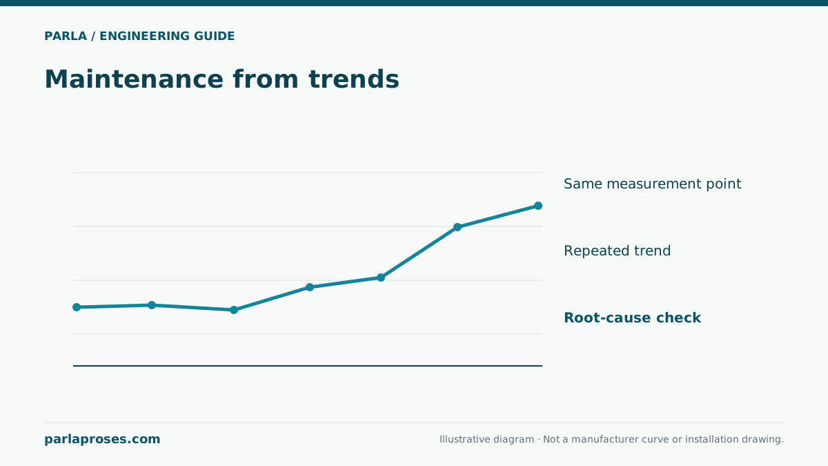
At an illustrative plant, overall vibration measured at the same bearing location and comparable duty rises from 2.0 to 3.6 mm/s RMS. The difference is 1.6 mm/s RMS, an increase of (3.6 − 2.0) / 2.0 × 100 = 80% relative to baseline. This is a strong trend signal for investigation, but 3.6 mm/s is not a universal failure or shutdown threshold. Machine type, mounting, manufacturer limits and the applicable evaluation method are necessary.
Assume flow also fell from 30 to 24 m³/h and suction pressure changed on the same shift. Do not call the rise a bearing failure outright. Check strainer, tank level, suction air ingress and valve position; inspect connections, base and coupling once safe isolation is established. Repeat the reading after restoring conditions to separate duty changes from equipment damage. This is a teaching example, not a real customer record.
| Record | Baseline | Later reading | Next check |
|---|---|---|---|
| Vibration, same location | 2.0 mm/s RMS | 3.6 mm/s RMS | 80% rise; interpret against manufacturer limits |
| Flow | 30 m³/h | 24 m³/h | Compare system and valve conditions |
| Suction pressure | Baseline logged | Changed | Inspect level, strainer and air ingress |
| Speed | Same | Same | Speed difference excluded in this example |
Make the measurement plan repeatable
Use a common sheet for equipment identity, bearing point, horizontal/vertical/axial direction, unit, sensor mounting method and operating band. Where appropriate, a specialist can review the spectrum and waveform alongside broadband overall values. Do not infer a certain root cause from one frequency peak; different mechanisms can look similar. Take a first reference reading at accepted commissioning conditions.
Set intervals according to criticality, failure history and rate of change. Maintain a basic interval for stable trends; increase inspection after a rise accompanied by temperature, power or leakage changes. Apply manufacturer or project acceptance limits to the correct machine class and mounting. Copying generic alarm thresholds from an unrelated table can cause a wrong decision.
Close an investigation with cause and outcome
A work order that merely says “bearing replaced” may not solve a repeating fault. Compare vibration, flow, pressure, power and temperature at comparable conditions before and after the intervention. Measure the result when an air leak is repaired. If coupling alignment is corrected, also review pipe strain and foundation condition. Recheck the trend at the next interval.
A critical plant with a standby pump may safely isolate the affected unit for planned inspection; without standby, operational risk differs. Maintenance strategy must cover hydraulic behaviour and safe shutdown together. Vibration monitoring then becomes a traceable decision record rather than a collection of isolated numbers.
Frequently asked questions
Does 3.6 mm/s require immediate shutdown?+
Not from that number alone. Consider machine class, manufacturer limit, mounting, trend and accompanying hazards.
Is rising vibration always a bearing fault?+
No. Flow change, cavitation, air, alignment and foundation issues are also possible. Measurements and inspection distinguish them.
Can readings at different speeds be compared?+
Not without context. Speed changes vibration behaviour; compare at the same duty where possible and document differences.
When should the first reading be taken?+
Establish a baseline at accepted commissioning duty, then compare the same location, direction and conditions.
Apply this assessment to your project.
Share your operating conditions, existing equipment and objective. Let’s assess product selection together with the technical documents.