Fire protection and design
Project information needed for fire pump selection
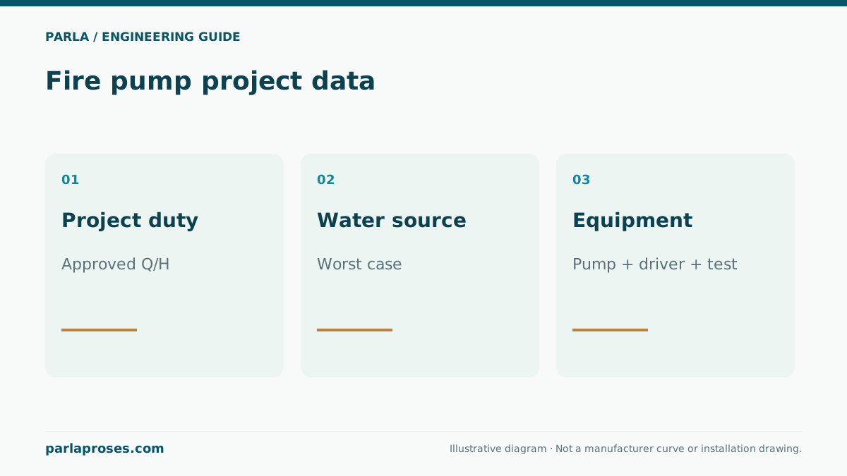
A fire pump cannot be selected from one ordinary booster pressure number. Assemble the approved hydraulic design, water source and equipment scope.
Illustrative engineering scenario · Assumptions are stated in the text.
AT A GLANCE
- Take flow and critical-point pressure from the approved hydraulic design.
- Check pump differential and the full curve at the least favourable source condition.
- Verify standard edition, driver, controller and acceptance scope with qualified project parties.
Start with the approved fire protection design
Fire pump duty comes from the facility’s approved fire protection hydraulic design. The designer establishes required flow, simultaneous demand, residual pressure at the critical point and the relevant pipe routes. Do not treat a catalogue’s maximum flow and maximum head as one simultaneous operating point. Ordinary booster controls are not a substitute for fire pump driver and controller requirements.
The enquiry file should identify applicable legislation, authority and insurer requirements, editions of governing standards, pump types and test and acceptance scope. NFPA 20 concerns installation of stationary fire pumps; hydraulic demand for sprinklers and other protection systems arises from their own applicable design rules. Confirm which standards and editions govern with the approving parties. This guide cannot replace approved fire engineering design.
Example: separate differential pump head
At a wholly illustrative duty, assume demand of 100 m³/h. At the most demanding remote outlet, assume 50 metres of residual pressure head, 18 metres elevation above pump discharge and 12 metres pipe loss at that flow. Required head at pump discharge is 50 + 18 + 12 = 80 metres. If the lowest dependable pressure at the pump suction connection is 10 metres of head at the same datum and duty, approximate differential pump head is 80 − 10 = 70 metres. These figures show only how the terms are combined.
Do not assume the 10 metres measured in a static condition persists at design demand; derive it from the verified worst dependable source condition at flow. Do not double-count suction losses in the same calculation. The real project must check the full pump curve, all relevant flows, shutoff pressure, minimum suction, pipe and fitting ratings, driver and controller requirements under the approved standard. This example recommends no model or fire protection performance.
| Term | Value | Location and interpretation |
|---|---|---|
| Remote residual pressure | 50 m | Assumed required value from approved design |
| Elevation difference | 18 m | Pump discharge to remote point |
| Line loss | 12 m | Assumed route at 100 m³/h |
| Discharge requirement | 80 m | 50 + 18 + 12 |
| Suction condition | 10 m | Lowest dependable source, same datum |
| Pump differential | 70 m | 80 − 10; actual curve checked separately |
Document water supply and pump-room conditions
Record source type, low and high water-level conditions, actual pressure at design demand, usable storage and water quality. A momentary static pressure reading from a mains connection is not by itself an adequate source test. For tank suction, assess level, inlet arrangement, pipe loss and manufacturer cavitation limits. Pump-room access, drainage, ventilation, temperature, lifting clearances and flood exposure belong in the project record.
Specify electrical supply or other driver provision together with controller, alarms and monitoring. Keep the main pump, any standby pump and jockey pump roles distinct; a jockey pump may compensate leakage but does not replace design fire flow. Document the required listing and approval conditions for the jurisdiction and project. “Fire” in a product-family label alone does not establish suitability.
Connect enquiry, acceptance and service records
Clarify required test points, certification expectations, supply type and installation boundaries along with design flow and pressure in the enquiry. Supplier, mechanical contractor and qualified designer must use the same hydraulic revision. A changed pipe route or water supply can require reselection. Record each party’s responsibility for component scope, installation and acceptance.
Compare commissioning results with approved design and applicable acceptance procedures. Log flow, suction and discharge pressure and driver data, and verify controller and alarm functions. Schedule subsequent inspection and maintenance under the governing local and project requirements. A system expected to function during a fire depends on the whole chain of water source, installation, control, acceptance and continuing service, not a catalogue entry alone.
Frequently asked questions
Does the jockey pump provide design fire flow?+
No. Its role in maintaining pressure against small leaks differs; the approved main-pump and system design provides fire demand.
Is static municipal supply pressure sufficient evidence?+
No. Verify the least favourable dependable source condition at design flow using test and project data.
Can I order a pump from the example’s 70 metres?+
No. The number is hypothetical. Verify flow, curve, source, controller, driver, standards and authority approval for the real project.
Does NFPA 20 determine sprinkler demand?+
NFPA 20 covers stationary fire pump installation; hydraulic demand comes from the protection-system design and applicable rules.
Apply this assessment to your project.
Share your operating conditions, existing equipment and objective. Let’s assess product selection together with the technical documents.